

ZeroPlus Technology Co Ltd
Carte de simulation de protocole ZeroPlus Type A
Carte de simulation de protocole ZeroPlus Type A
SKU: PROT-SIM-A
Impossible de charger la disponibilité du service de retrait

Key Features
Overview
Downloads
Why Engineers Choose The Carte de simulation de protocole ZeroPlus Type A
Protocol Validation
Development Efficiency
Educational Training
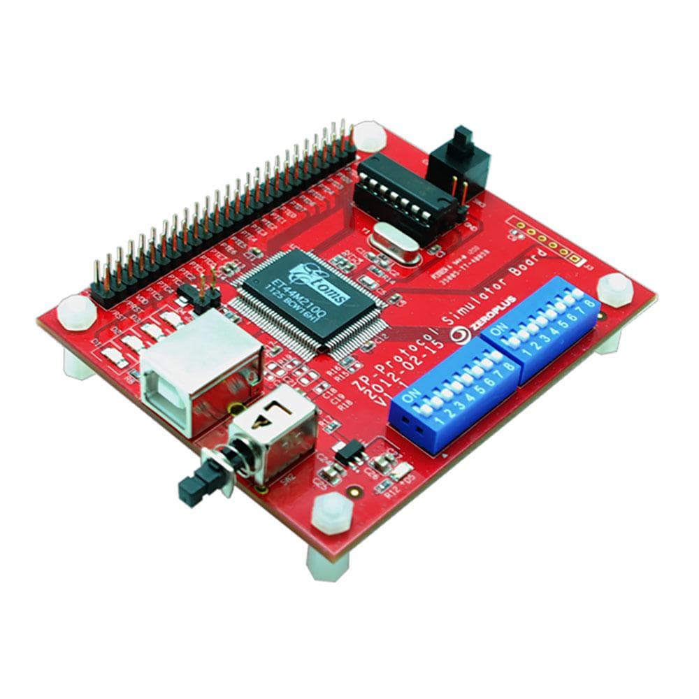
La carte simulateur de protocole A simule des paquets de données pour quarante-six protocoles différents (voir description ci-dessous).
La carte peut envoyer un seul paquet, les données de chaque paquet étant déterminées à partir de l'entrée numérique de la carte. Alternativement, la carte peut être configurée pour envoyer un flux continu de paquets contenant les mêmes données.
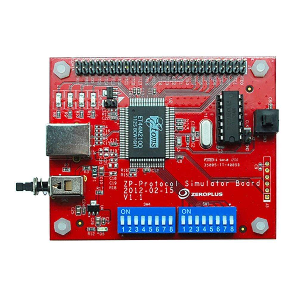
Un commutateur DIP sélectionne le protocole.
| General Information | |
|---|---|
Part Number (SKU) |
PROT-SIM-A
|
Manufacturer |
|
| Physical and Mechanical | |
Weight |
0.5 kg
|
| Other | |
EAN |
5055383620432
|
Frequently Asked Questions
Have a Question?
-
Are any additional protocols supported beyond the Protocol Simulator Board A?
Yes, Zeroplus offers the Protocol Simulator Board B which supports a different set of nearly 100 protocols. Board B includes protocols such as eMMC, SD3.0, HDMI_CEC, KNX, KEELOQ, Differential Manchester, and numerous other specialised communication standards. The two boards complement each other, providing coverage across different protocol families and applications for comprehensive testing coverage.
-
How does this compare to software-based protocol simulators?
Hardware simulators like the Protocol Simulator Board A provide authentic electrical timing and signal characteristics that software simulators cannot replicate. This includes proper rise/fall times, impedance matching, and real-world signal integrity aspects crucial for comprehensive logic analyser testing and validation.
-
Can I modify packet content in the continuous stream mode?
The continuous stream mode transmits pre-configured packet patterns specific to each protocol. Packet content modification typically requires single packet mode where digital inputs determine the data content. Some protocols may offer limited content variation through DIP switch sub-settings.
-
What documentation comes with the Protocol Simulator Board A?
The board includes a comprehensive user guide detailing supported protocols, DIP switch settings, connection diagrams, and example configurations. Additional resources include protocol timing diagrams and sample logic analyser capture examples.
-
Is this suitable for educational use and training?
Absolutely. The Protocol Simulator Board A serves as an excellent educational tool for teaching digital communication protocols and logic analyser usage. It provides students with consistent, repeatable protocol signals for learning analysis techniques without complex hardware requirements.
-
How do I connect the simulator board to my logic analyser?
Connect the protocol output pins to your logic analyser's input channels using standard probe leads or flying leads. Ensure proper ground connections between the board and logic analyser. The board provides clearly marked test points for easy probe attachment.
-
What power supply requirements does the board have?
The Protocol Simulator Board A typically requires 5V DC power supply. Check the board documentation for specific current requirements and connector types. Most setups can power the board from the logic analyser's auxiliary power output or a standard bench power supply.
-
What's the difference between single packet and continuous stream modes?
Single packet mode transmits one data packet when triggered, with packet content determined by digital inputs to the board. Continuous stream mode repeatedly transmits identical packets continuously. Single mode suits trigger testing whilst continuous mode benefits long-term protocol analysis and decoder validation.
-
Can this simulator board work with non-Zeroplus logic analysers?
Yes, the Protocol Simulator Board A outputs standard TTL/CMOS logic levels compatible with most logic analysers including Saleae, Acute Technology, and other manufacturers' devices. Ensure your logic analyser supports the appropriate voltage thresholds and sampling rates.
-
How do I select different protocols on the simulator board?
Protocol selection uses a DIP switch array located on the board. Each switch position corresponds to a specific protocol. Simply set the switches to the desired protocol code (referenced in the included documentation) and power cycle the board to activate the selected protocol.
-
What protocols does the Protocol Simulator Board A support?
The board supports 46 different communication protocols including I2C, SPI, UART (RS-232C/422/485), CAN 2.0B, USB 1.1, LIN 2.1, FlexRay 2.1A, ModBus, JTAG 2.0, LCD1602, LCD12864, and numerous other embedded system and automotive standards. The complete protocol list covers common digital communication methods plus specialised industrial interfaces.