


Mikroelektronika d.o.o.
Current Limit 6 Click Board™
Current Limit 6 Click Board™
SKU: MIKROE-4915
Couldn't load pickup availability

Overview
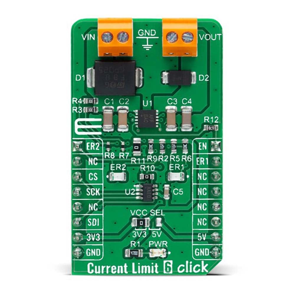
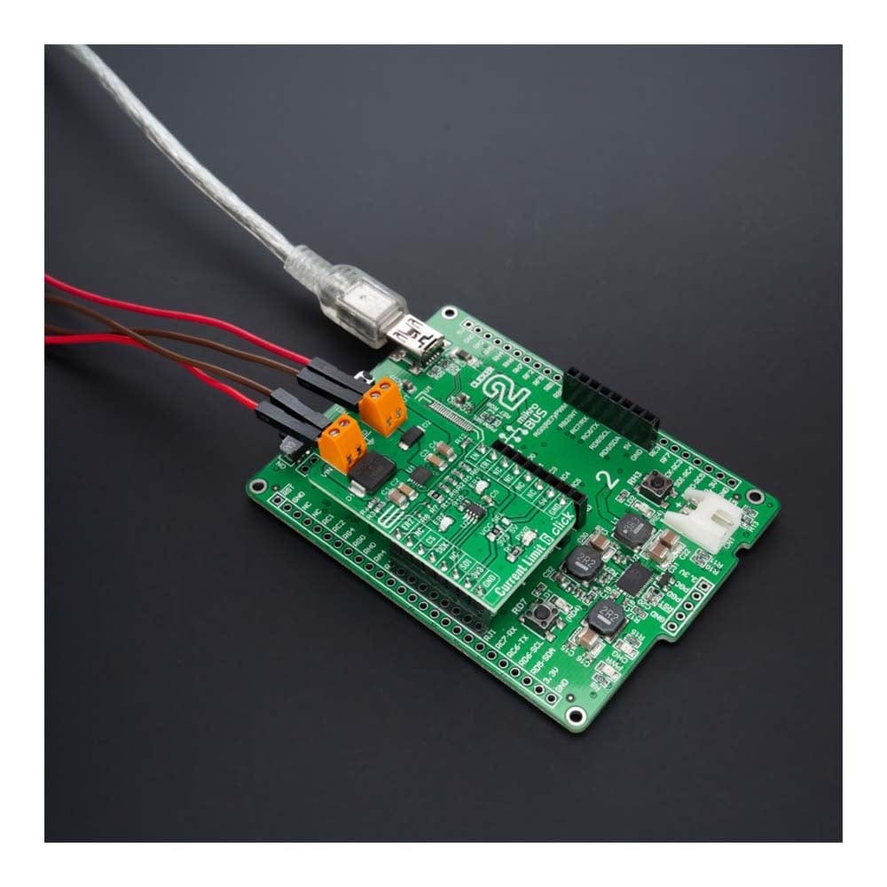
The Current Limit 6 Click Board™ is a compact add-on board representing a current-limiting solution. This board features the MAX17608, adjustable overvoltage, and overcurrent protection device from Maxim Integrated, now part of Analog Devices. This Click board™ is ideal for protecting systems with the flexible input overvoltage protection range from 4.5V to 60V, and the adjustable input under-voltage protection range is 4.5V to 59V. Also, the maximum current limit is 1A and can be programmed through a digital potentiometer MAX5401. When the device current reaches the programmed threshold, the device prevents further current increases by modulating the FET resistance.
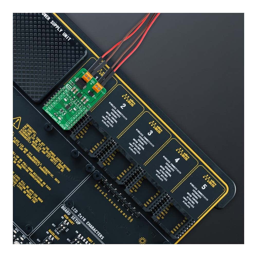
The Current Limit 6 Click Board™ is suitable for applications in portable equipment, process instrumentation, and condition monitoring, or with power supplies, protecting them in a short circuit or other overload conditions.
Downloads
How Does The Current Limit 6 Click Board™ Work?
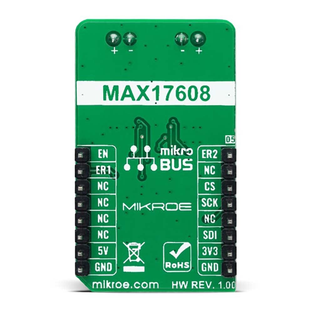
The Current Limit 6 Click Board™ as its foundation uses the MAX17608, a current-limiting device with an adjustable overvoltage and overcurrent protection feature from Maxim Integrated, now part of Analog Devices. The MAX17608 offers flexible protection boundaries for systems against input voltage ranging from 4.5V to 60V and limits the output load current to a programmed level (up to 1A). The devices also feature two internal MOSFETs connected in series, with a low cumulative RON of 260mΩ typical. Input undervoltage protection can be programmed between 4.5V and 59V, while the overvoltage protection can be independently programmed between 5.5V and 60V (default Click board™ configuration is 4.5V for UVLO and 14V for OVLO). Additionally, the MAX17608 has an internal default undervoltage lockout set at 4V typical.
The current-limit switch is virtually ubiquitous in system control and provides a safe means for regulating the current delivered to a load circuit. It allows the load current to increase to a programmed limit but no higher. Typically, the current limit is a function of the voltage across an external resistor, and this voltage serves as the reference for an internal current-limiting amplifier. By replacing the resistor with a digital potentiometer, you can easily program the current limit as performed on this Click board™. For this purpose, the digital potentiometer MAX5401 from Maxim Integrated, which communicates with the MCU via 3-Wire SPI serial interface, is used to set the resistance on the MAX17608 SETI pin, adjusting the current limit for the switch between 0.1A to 1 A.
This current limiter offers several operational modes, selectable through a populated jumper labelled as R11 connected to the CLMD pin of the MAX17608. In a default configuration, this pin is connected to the ground, representing the Continuous mode of operation. When R11 is replaced with a 150kΩ resistor, this Click board™ is in the Latch-off mode, and when the user leaves this pin unconnected Autoretry mode of operation is activated. More information on the operational modes can be found in the attached datasheet.
The Current Limit 6 Click Board™ can be enabled or disabled through the EN pin routed to the PWM pin of the mikroBUS™ socket; hence, offering a switch operation to turn ON/OFF power delivery to the connected load. It also provides communication signals routed to the INT and AN pins of the mikroBUS™ socket, alongside its LED indicators labelled as ER1 and ER2, to indicate different operational and fault signals such as FLAG and UVOV signals. Besides, the MAX17608 also offers internal thermal shutdown protection against excessive power dissipation.
The Current Limit 6 Click Board™ can operate with both 3.3V and 5V logic voltage levels selected via the VCC SEL jumper. This way, it is allowed for both 3.3V and 5V capable MCUs to use the communication lines properly. However, the Click board™ comes equipped with a library containing easy-to-use functions and an example code that can be used, as a reference, for further development.
SPECIFICATIONS
| Type | Power Switch |
| Applications | The Current Limit 6 Click Board™ be used for applications in portable equipment, process instrumentation, and condition monitoring, or with power supplies, protecting them in a short circuit or other overload conditions |
| On-board modules | MAX17608 - current-limiting device with an adjustable overvoltage and overcurrent protection feature from Maxim Integrated, now part of Analog Devices |
| Key Features | OVLO/UVLO and reverse voltage protection, programmable current limiting up to 1A, wide input-supply range up to 60V, thermal overload protection, operational and fault signals indicators, and more |
| Interface | GPIO,SPI |
| Compatibility | mikroBUS |
| Click board size | M (42.9 x 25.4 mm) |
| Input Voltage | 3.3V or 5V,External |
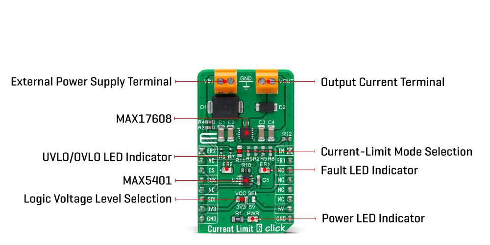
PINOUT DIAGRAM
This table shows how the pinout for the Current Limit 6 Click Board™ corresponds to the pinout on the mikroBUS™ socket (the latter shown in the two middle columns).
| Notes | Pin | Pin | Notes | ||||
|---|---|---|---|---|---|---|---|
| UVLO/OVLO Indicator | ER2 | 1 | AN | PWM | 16 | EN | Enable |
| NC | 2 | RST | INT | 15 | ER1 | Fault Indicator | |
| SPI Chip Select | CS | 3 | CS | RX | 14 | NC | |
| SPI Clock | SCK | 4 | SCK | TX | 13 | NC | |
| NC | 5 | MISO | SCL | 12 | NC | ||
| SPI Data IN | SDI | 6 | MOSI | SDA | 11 | NC | |
| Power Supply | 3.3V | 7 | 3.3V | 5V | 10 | 5V | Power Supply |
| Ground | GND | 8 | GND | GND | 9 | GND | Ground |
ONBOARD SETTINGS AND INDICATORS
| Label | Name | Default | Description |
|---|---|---|---|
| LD1 | PWR | - | Power LED Indicator |
| LD2 | ER2 | - | UVLO/OVLO LED Indicator |
| LD3 | ER1 | - | Fault LED Indicator |
| JP1 | VCC SEL | Left | Logic Level Voltage Selection 3V3/5V: Left position 3V3, Right position 5V |
| R11 | R11 | Populated | Current-Limit Mode Selection Jumper |
CURRENT LIMIT 6 CLICK ELECTRICAL SPECIFICATIONS
| Description | Min | Typ | Max | Unit |
|---|---|---|---|---|
| Supply Voltage VCC | 3.3 | - | 5 | V |
| External Supply Voltage VIN | 4.5 | - | 60 | V |
| Output Current-Limit Range | 0.1 | - | 1 | A |
| Operating Temperature Range | -40 | +25 | +125 | °C |
| General Information | |
|---|---|
Part Number (SKU) |
MIKROE-4915
|
Manufacturer |
|
| Physical and Mechanical | |
Weight |
0.02 kg
|
| Other | |
EAN |
8606027389849
|
Frequently Asked Questions
Have a Question?
Be the first to ask a question about this.