


Mikroelektronika d.o.o.
WiFi 9 Click Board™
WiFi 9 Click Board™
SKU: MIKROE-3666
Couldn't load pickup availability
Overview
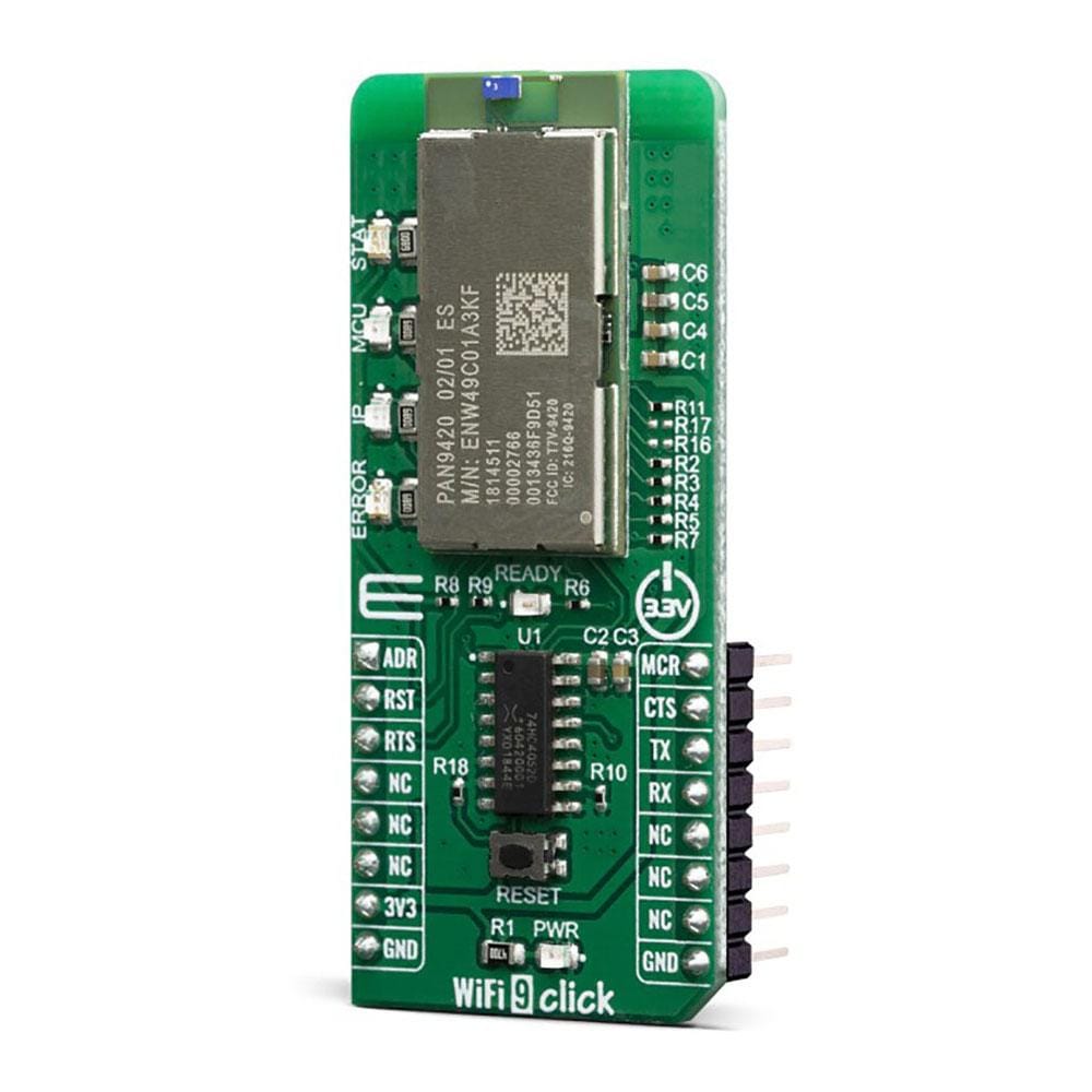
The WiFi 9 Click Board™ is a fully embedded stand-alone Wi-Fi module, equipped with the PAN9420 a 2.4 GHz ISM band WiFi-embedded module which includes a wireless radio and an MCU for easy integration of WiFi connectivity into various electronic devices. This module combines a high-performance CPU with Wireless radio and integrated memory, which offers many features like webpage storing of HTML or image data, the possibility to work in the access point or infrastructure mode, and dual UART interface for communication with the host controllers.
Downloads
The WiFi 9 Click Board™ features the PAN9420 a 2.4 GHz 802.11 b/g/n embedded Wi-Fi module with integrated stack and API that minimizes firmware development and includes a full security suite. The module is specifically designed for highly integrated and cost-effective applications. The module includes a fully shielded case, integrated crystal oscillators, and a chip antenna.
How Does The WiFi 9 Click Board™ Work?
The WiFi 9 Click Board™ comes equipped with the PAN9420, a full embedded Wi-FI module from Panasonic. The module combines a high-performance CPU, high-sensitivity wireless radio, baseband processor, medium access controller, encryption unit, boot ROM with patching capability, internal SRAM, and in-system programmable flash memory. The module's integrated QSPI flash memory is available to the application for storing web content such as HTML pages or image data.
Parallel support of access point and infrastructure mode allows easy setup of simultaneous Wi‑Fi connections from the module to smart devices and home network routers. The pre‑programmed Wi-Fi SoC firmware enables client (STA), micro access point (µAP), and Ad‑hoc mode (Wi-Fi Direct) applications. With the transparent mode, raw data can be sent from the UART to the air interface to smart devices, web servers, or PC applications.
For working with PAN9420 module at your disposal are two data UART interfaces, one for command and another for transparent data. In order to enable simultaneous communication between the module and host MCU through one UART on mikroBUS™ socket we have added 74HC4052 multiplexer from Nexperia USA Inc.
For selecting between UART0/UART1 you may use ADR pin (ADDRES):
| ADR pin state | Module pins | Selected Interface |
|---|---|---|
| LOW | TXD0/RXD0 | UART0 |
| HIGH | TXD/RXD | UART1 |
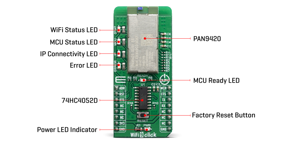
On the WiFi 9 Click Board™ several status LED's are implemented for easiest visual monitoring of the module states like MCU heartbeat, IP connectivity, Errors, WiFi connection and Booting.
The PAN9420 supports Over-the-Air firmware updates. In order to make use of this feature, the customer needs to ensure that the appropriate preconditions are fulfilled and that a suitable environment is provided, particularly with regard to:
- Module configuration
- Utilization of the related module interface commands
- Server infrastructure and application
The PAN9420 module is operated at 3.3V. Having in mind its absolute maximum ratings, it is not advisable to use the Click board™ with MCUs that use logic voltage levels up to 5V.
SPECIFICATIONS
| Type | WiFi |
| Applications | The WiFi 9 Click Board™ all necessary IoT functionality perfectly suited for IoT applications which require simultaneous support of Access-Point- and Infrastructure mode |
| On-board modules | Full featured standalone WiFi module PAN9420 from Panasonic, a 2.4 GHz ISM module which includes a wireless radio and an MCU |
| Key Features | Full-featured embedded network stack, integrated webserver, over-the-air firmware updates, integrated QSPI flash memory for customer web contents or configuration file storing |
| Interface | GPIO,UART |
| Compatibility | mikroBUS |
| Click board size | L (57.15 x 25.4 mm) |
| Input Voltage | 3.3V |
PINOUT DIAGRAM
This table shows how the pinout of the WiFi 9 Click Board™ corresponds to the pinout on the mikroBUS™ socket (the latter shown in the two middle columns).
| Notes | Pin | Pin | Notes | ||||
|---|---|---|---|---|---|---|---|
| Address Select | ADR | 1 | AN | PWM | 16 | MCU | MCU Reset |
| Reset | RST | 2 | RST | INT | 15 | CTS | Clear to Send |
| Request to Send | RTS | 3 | CS | RX | 14 | TX | UART Transmit |
| NC | 4 | SCK | TX | 13 | RX | UART Receive | |
| NC | 5 | MISO | SCL | 12 | NC | ||
| NC | 6 | MOSI | SDA | 11 | NC | ||
| Power Supply | 3.3V | 7 | 3.3V | 5V | 10 | NC | |
| Ground | GND | 8 | GND | GND | 9 | GND | Ground |
ONBOARD SETTINGS AND INDICATORS
| Label | Name | Default | Description |
|---|---|---|---|
| T1 | RESET | - | Reset button for firmware rebooting |
| LD1 | MCU | - | MCU status (heartbeat) LED |
| LD2 | IP | - | IP connectivity (allocated IP) status LED |
| LD3 | ERROR | - | Error (active during booting) status LED |
| LD4 | STAT | - | Wireless (Wi-Fi) status LED |
| LD5 | READY | - | MCU ready (booting ready) status LED |
| LED GREEN | PWR | - | Power LED Indicator |
WIFI 9 CLICK LED STATUS LEGEND
| LED | Application | LED Function |
|---|---|---|
| MCU | OFF: Shut-off BLINK (1sec): Firmware active |
MCU status (heartbeat) |
| IP | OFF: no IP assigned ON: IP assigned |
IP connectivity in Infrastructure mode |
| ERROR | OFF: no error ON: error appeared |
MCU Firmware Error |
| STAT | OFF: no AP connection BLINK (0.2 s): Scanning for AP BLINK (0.4 s): trying to connect to AP BLINK (1.2 s): WLAN Error ON: Associated with AP |
WLAN connectivity in Infrastructure mode |
| READY | OFF: Shut-off ON: Firmware ready | Firmware application is ready |
| PWR | ON: Click board is powered on OFF: Click boards is missing power |
Power LED Indicator |
| General Information | |
|---|---|
Part Number (SKU) |
MIKROE-3666
|
Manufacturer |
|
| Physical and Mechanical | |
Weight |
0.022 kg
|
| Other | |
EAN |
8606018716487
|
Frequently Asked Questions
Have a Question?
Be the first to ask a question about this.