


Mikroelektronika d.o.o.
MIC 2 Click Board™
MIC 2 Click Board™
SKU: MIKROE-3445
Couldn't load pickup availability


Overview
The MIC 2 Click Board™ is equipped with a small electret microphone, accompanied by a suitable preamplifier circuit. The small electret microphone is not capable of providing sufficient line-level output; therefore, the pre-amp has to be used. The pre-amp circuit consists of a dual op-amp and a digitally controlled potentiometer IC. Thanks to the AD5171, it is possible to control the feedback loop gain of the MCP6022 op-amp over the I2C interface, in 64 discrete steps. The AD5171 digital potentiometer IC can lock-out its wiper by means of OTP fuse bit: once locked, it will permanently retain the programmed value.
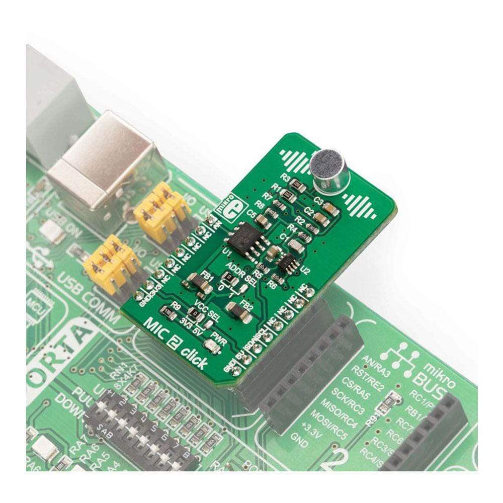
The MIC 2 Click Board™ is supported by a mikroSDK compliant library, which includes functions that simplify software development. This Click Board™ comes as a fully tested product, ready to be used on a system equipped with the mikroBUS™ socket.
Downloads
The small omnidirectional electret microphone features a reasonably flat frequency response, and it can be used within the frequency range between 100 Hz and 20 kHz. This range is perfectly suited for audio and/or speech applications. Due to its small size, programmable gain, low power supply, and reasonably good signal-to-noise ratio, the MIC 2 Click Board™ can be used for development of various audio and speech-related applications: speech or audio digitizing, digital audio monitoring and surveillance, digital "bugs", etc.
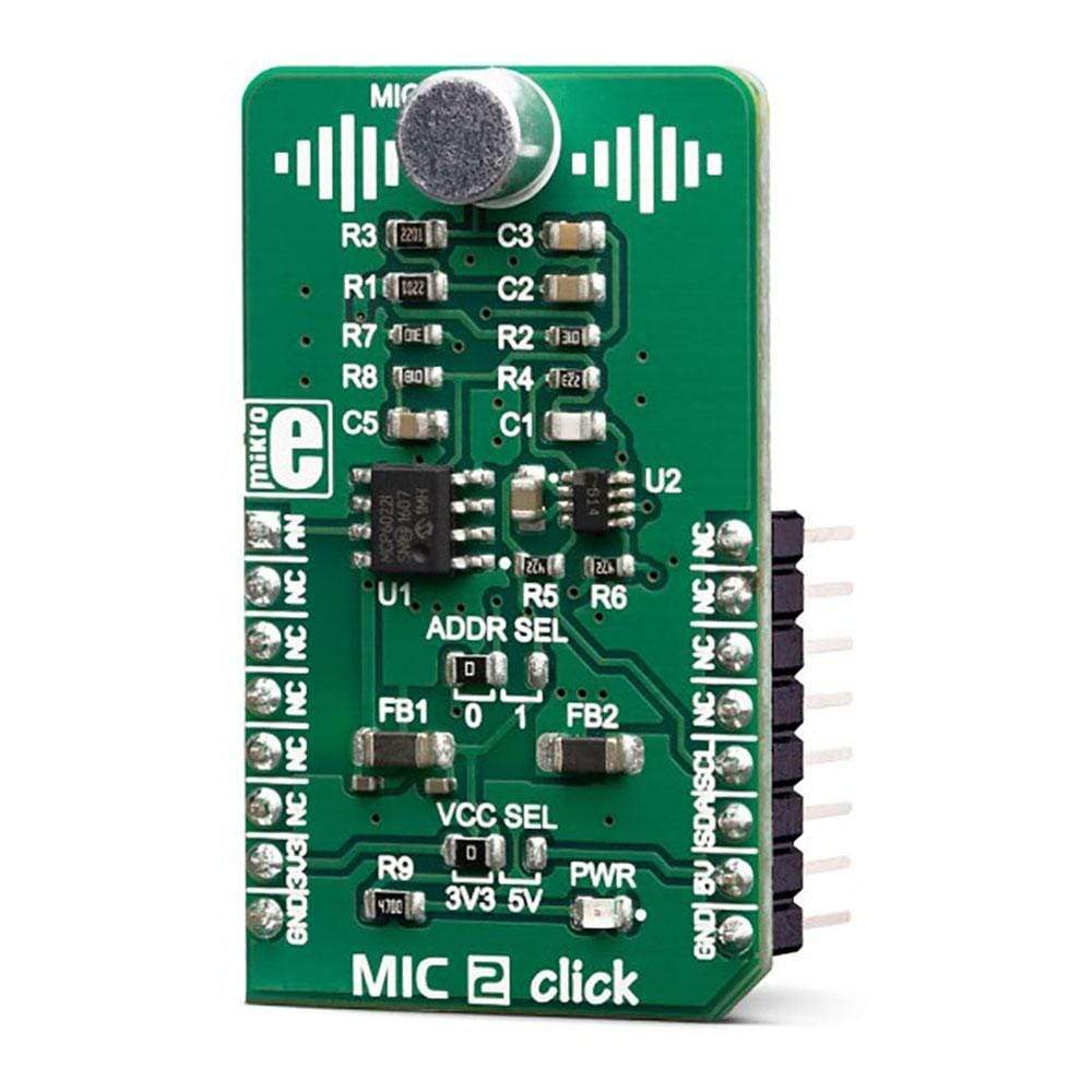
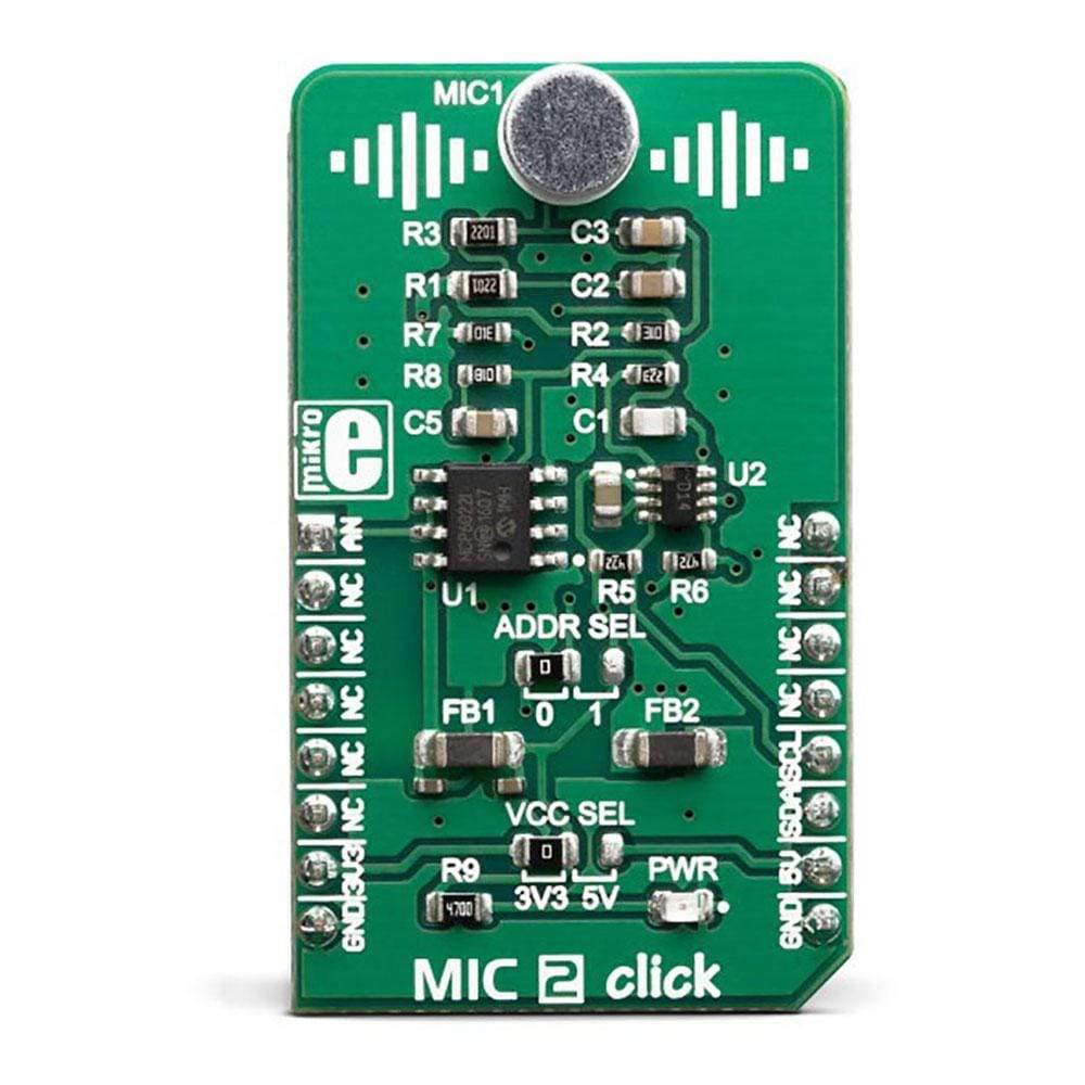
How Does The MIC 2 Click Board™ Work?
The MIC 2 Click Board™ is designed around a small omnidirectional electret microphone, accompanied by a digitally controlled pre-amp section. The pre-amp consists of the MCP6022, a dual, rail-to-rail, low noise operational amplifier from Microchip. This op-amp has a wide bandwidth of 10MHz, very low noise, and extremely low total harmonic distortion (THD). These features make it perfectly suitable to be used to build a microphone pre-amplifier (pre-amp). By adding a digital potentiometer IC in the feedback loop, it is possible to set the gain ratio by the host MCU.
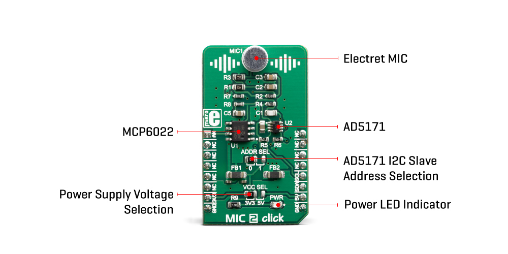
The AD5171, a digital potentiometer IC with 64 positions from Analog Devices is used in the feedback loop to digitally control the gain ratio. This device contains an OTP memory (a fuse) which can be used to lock the wiper in a permanent position. The wiper data can be changed indefinitely until the internal protection fuse is blown. This can be done by a special command. However, the Click board™ must be operated at 5V in order to successfully blow up the fuse and lock down the wiper position permanently. Please consult the AD5171 for more details about the OTP memory programming and permanent lock-down of the wiper position.
The AD5171 uses the I2C interface to communicate with the host MCU. The slave I2C address of this device can be changed using the SMD jumper, labelled as ADDR SEL. This jumper sets the LSB of the address, allowing it to be selected between 0b0101100x, and 0b0101101x, where (x) represents the R/W bit. The datasheet of the AD5171 offers a comprehensive explanation of its operation. However, it is supported by a mikroSDK compatible set of libraries. These functions greatly simplify the use, ensuring that the accidental lock-down is avoided if not wanted.
One half of the MCP6022 is configured as a non-inverting amplifier, with the digital potentiometer connected as a rheostat in its feedback loop. The digital rheostat affects the feedback loop gain, allowing the host MCU to control it over the I2C interface. The input of the op-amp is biased by a voltage divider, so it stays at half the power supply voltage when there is no signal. This way when the signal appears at the input, it can swing both down to 0V and up to VCC. A minimum gain of the op-amp is 23. It can be increased as the AD5171 is moved away from the 0 position. After power ON, the wiper of the AD5171 is in the middle position (i.e. 25K, if it is not locked down to some other value).
The second op-amp of the MCP6022 serves as a unity-gain buffer, allowing the host MCU to sample the output over the AN pin of the mikroBUS™. Depending on the applied gain ratio, the output voltage may peak up to VCC. Therefore, care should be taken when selecting the voltage for the Click board™.
The power supply voltage for the MIC 2 Click Board™ can be selected using the VCC SEL jumper on the Click board™. As already mentioned, please avoid programming the OTP bit, if the supply voltage is set to 3.3V.
SPECIFICATIONS
| Type | Microphone |
| Applications | It can be used for development of various audio and speech-related applications: speech or audio digitizing, digital audio monitoring and surveillance, digital ""bugs"", etc. |
| On-board modules | MCP6022, a dual, rail-to-rail, low noise operational amplifier from Microchip; AD5171, a digital potentiometer IC with 64 positions from Analog Devices. |
| Key Features | Programmable gain, low noise, very low THD, possibility to permanently lock-down gain ratio if required, gain control in 64 discrete steps, onboard electret omnidirectional microphone, etc. |
| Interface | Analog,I2C |
| Compatibility | mikroBUS |
| Click board size | M (42.9 x 25.4 mm) |
| Input Voltage | 3.3V or 5V |
PINOUT DIAGRAM
This table shows how the pinout of the MIC 2 Click Board™ corresponds to the pinout on the mikroBUS™ socket (the latter shown in the two middle columns).
| Notes | Pin | Pin | Notes | ||||
|---|---|---|---|---|---|---|---|
| Amplifier OUT | AN | 1 | AN | PWM | 16 | NC | |
| NC | 2 | RST | INT | 15 | NC | ||
| NC | 3 | CS | RX | 14 | NC | ||
| NC | 4 | SCK | TX | 13 | NC | ||
| NC | 5 | MISO | SCL | 12 | SCL | I2C Clock | |
| NC | 6 | MOSI | SDA | 11 | SDA | I2C Data | |
| Power Supply | 3V3 | 7 | 3.3V | 5V | 10 | 5V | Power Supply |
| Ground | GND | 8 | GND | GND | 9 | GND | Ground |
MIC 2 CLICK ELECTRICAL SPECIFICATIONS
| Description | Min | Typ | Max | Unit |
|---|---|---|---|---|
| Microphone sensitivity (0dB = 1V/Pa) | -45 | - | -39 | dB |
| Signal to noise ratio (SNR) | - | 58 | - | dBA |
| Frequency range | 100 | - | 20k | Hz |
| Pre-amplifier gain ratio | 23 | - | 73 | X |
ONBOARD SETTINGS AND INDICATORS
| Label | Name | Default | Description |
|---|---|---|---|
| LD1 | PWR | - | Power LED indicator |
| JP1 | ADDR SEL | Left | I2C Slave address LSB selection: left position GND (0), right position VCC (1) |
| JP2 | VCC SEL | Left | Power supply voltage selection: left position 3.3V, right position 5V |
| General Information | |
|---|---|
Part Number (SKU) |
MIKROE-3445
|
Manufacturer |
|
| Physical and Mechanical | |
Weight |
0.019 kg
|
| Other | |
EAN |
8606018714926
|
Frequently Asked Questions
Have a Question?
Be the first to ask a question about this.