
Mikroelektronika d.o.o.
Smart Buck Click Board™
Smart Buck Click Board™
SKU: MIKROE-3113
Couldn't load pickup availability


Overview
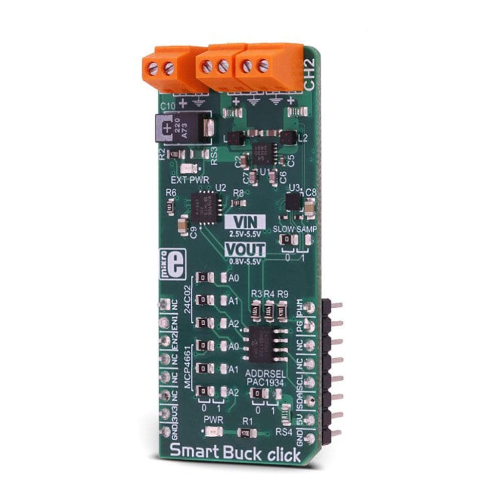
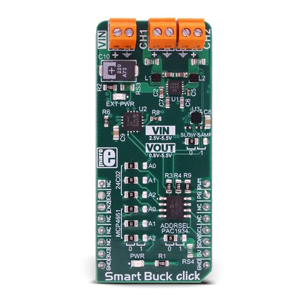
The Smart Buck Click Board™ is the two-channel step-down DC/DC converter and regulator, with plenty of additional functions. It can provide voltage measurement at each of its two programmable voltage outputs, as well as the measurement of the current consumption. In addition, it can also provide power consumption measurements of the Smart Buck Click Board™, both at the mikroBUS +5V power rail, and the external voltage input terminal. Finally, there is 2kbit of EEPROM at disposal, which can be used for logging the measurements, storage of the working parameters, or any other type of general purpose data.
Downloads
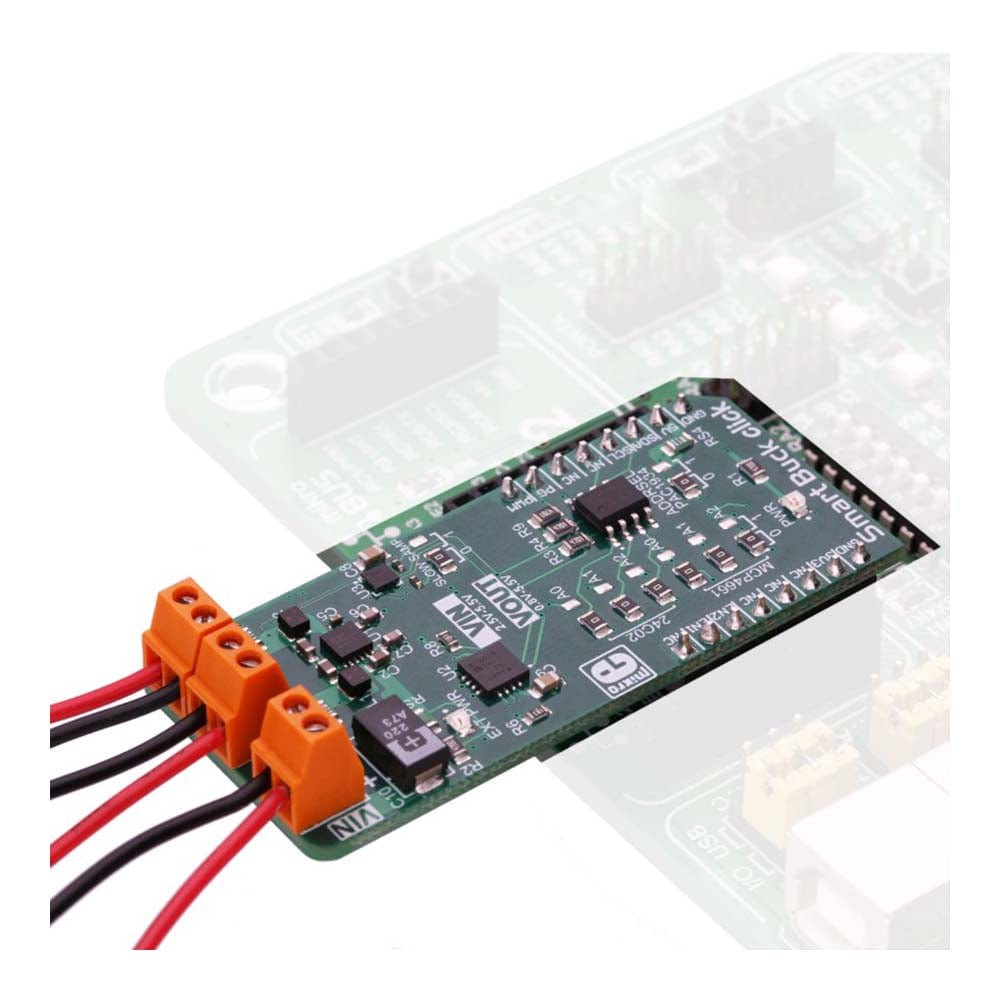
The external power supply should be connected to the VIN terminal, with the voltage between 2.5 and 5.5V. The Smart Buck Click Board™ provides two independent output voltage channels, each with the ability to output a regulated voltage in the range between 0.8V up to 5.5V. It is able to provide up to 800mA for the connected load at each of the output terminals. With the ability to programmatically set both voltage values independently while providing reasonably high current, offering 2kbit of non-volatile memory and voltage and current monitoring for both outputs and two input voltage points, Smart Buck is a perfect solution for many different applications, especially well suited for the embedded and IoT applications.
How Does The Smart Buck Click Board™ Work?
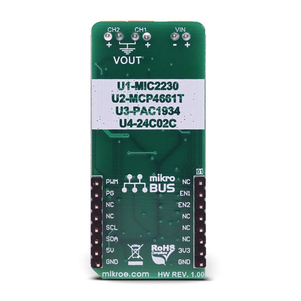
The heart of the Smart Buck Click Board™ is the MIC2230, a dual synchronous step-down DC/DC regulator, by Microchip. This dual buck converter and voltage regulator offers two independent outputs with their own feedback loops, which allow both outputs to be set to a specific voltage, independently. The dual buck converter works in synchronous PWM mode, whenever the load drains more than 100mA. The operating mode of the converter is switched to so-called Trickle mode when the connected load drains less than 100mA. Although highly efficient for the light loads, this mode has its downsides, such as the slightly increased ripple and increased voltage regulation tolerance. For most cases (when the supplied device enters the standby mode, when the system is suspended, and similar) this is sufficient, but for some critical low current applications, the MIC2230 can be set to always operate in synchronous PWM mode at 2.5MHz, with the output voltage ripple as low as 7mV. To set the PWM mode regardless of the connected load, it is sufficient to pull the FPWM pin of the MIC2230 to a LOW logic level. The FPWM pin is routed to the PWM pin of the mikroBUS™.
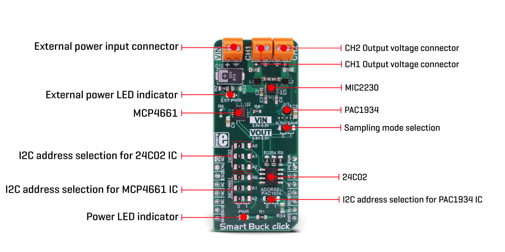
Two FB pins of the MIC2230 are used to determine the output voltage at each of the outputs. There is a digitally controlled dual potentiometer IC on the Click board™, labelled as the MCP4661. This IC is a dual 8-bit digital potentiometer with the non-volatile memory and the WiperLock function, from Microchip. The WiperLock function allows permanent storage of the wiper position in the internal EEPROM of the MCP4661 IC. The internal digital potentiometers are connected as the rheostats, acting as the second, variable resistor of the feedback voltage dividers. This allows setting the output voltage, by programming the digital potentiometer values via the I2C interface. The I2C slave address of the MCP4661 IC can be set by the SMD jumpers, labelled as A0 to A2, grouped under the MCP4661 label.
For the power monitoring purposes, Smart Buck click uses the PAC1934, a four-channel DC power and energy monitor with the accumulator, from Microchip. Due to its high degree of integration and an integrated real-time offset and gain compensation circuitry, this device requires only a few sensing resistors to be able to monitor the voltage and sense the current consumption. This IC also contains a high-performance digital section, accessible via the I2C interface, which is used to integrate the measurement results and provide on-chip power calculations, reducing the processing load of the MCU. Single Shot and Continous modes are at disposal, allowing fine-tuning of its functionality. It has four channels of which two are used to monitor current and voltage on the two output terminals. One of the channels is used to monitor a power consumption on the input supply terminal, and finally, one channel monitors the +5V rail of the mikroBUS™. This allows power efficiency of the converter to be easily calculated, as well as the power consumption of the Smart Buck Click Board™.
The sensing elements which are connected to the PAC1934 are low-value resistors, ranging from 0.05Ω up to 0.11Ω. The channel inputs are differential pairs, which are implemented as the Kelvin connection to sensing resistors. Kelvin connection allows very precise measurements, since the voltage drop along the sensor traces due to their resistance, is eliminated. The I2C address of the PAC1934 monitoring IC can also be changed by the onboard SMD jumper, labelled as PAC1934 ADDR SEL. The sampling rate can also be changed by switching the SLOW SAMP jumper to either 0 or 1. Switching it to 1 will enable the slow sampling feature of the PAC1934, enforcing the sample rate of 8sps, regardless of the CTRL register content. The default sampling rate with the default jumper position (SLOW SAMP at 0) is 1024sps.
An EEPROM module is included onboard as an extra feature of the Smart Buck click. The 24C02C, an I2C serial EEPROM from Microchip, with the density of 2kbit is used on the Click board™ to provide storage for any type of data. It has 2kbit of memory, organized in 256 x 8bit words, which translates to 256 bytes of non-volatile memory, which can be used to either store working parameters, or some other application-specific data. The outstanding quality of the module allows up to one million of write/erase cycles and data retention of more than 200 years. All its inputs are protected from noise with the Schmitt triggers, and the module supports fast speed I2C mode, up to 400kHz. The I2C address of this device is also configurable by a set of SMD jumpers labelled as A0 to A2, grouped under the 24C02 label.
The input/output facilities include two terminals labelled as the CH1 and CH2, which output the step-down voltage in the range of 0.8V up to 5.5V, as previously mentioned. A notice should be taken that an input voltage up to 5.5V should be connected at the input terminal labelled as the VIN, in order to get a voltage at the output. Also, it should be noted that the output voltage should be always programmed to a value lower than the input voltage. The presence of an external power supply at the VIN terminal will be indicated by a red LED, labelled as EXT PWR. The I2C protocol is used for all the sections of Smart Buck click. The required pull-up resistors are included onboard. The Click board™ allows interfacing with 3.3V MCUs, only.
SPECIFICATIONS
| Type | Buck |
| Applications | The Smart Buck Click Board™ can be used to digitally convert input voltage signals up to 3.3V so that the signals can be analyzed by various mathematical models and algorithms on the CPU or MCU. |
| On-board modules | MIC2230, a dual synchronous step-down DC/DC regulator; MCP4661, an 8-bit dual digital potentiometer with non-volatile memory; PAC1934, a four-channel DC power and energy monitor with accumulator; 24C02C, a 2kbit serial EEPROM, all devices from Microchip |
| Key Features | Digitally controlled voltage levels on two independent outputs, low output voltage ripple, reasonably high output current capability, four power monitoring channels by a dedicated monitoring IC, 2kbit of non-volatile memory onboard, and more |
| Interface | I2C |
| Compatibility | mikroBUS |
| Click board size | L (57.15 x 25.4 mm) |
| Input Voltage | 3.3V,5V |
PINOUT DIAGRAM
This table shows how the pinout on Smart Buckclick corresponds to the pinout on the mikroBUS™ socket (the latter shown in the two middle columns).
| Notes | Pin | Pin | Notes | ||||
|---|---|---|---|---|---|---|---|
| NC | 1 | AN | PWM | 16 | PWM | PWM Mode | |
| Chip Enable ch1 | EN1 | 2 | RST | INT | 15 | PG | Power Good INT |
| Chip Enable ch2 | EN2 | 3 | CS | RX | 14 | NC | |
| NC | 4 | SCK | TX | 13 | NC | ||
| NC | 5 | MISO | SCL | 12 | SCL | I2C Clock | |
| NC | 6 | MOSI | SDA | 11 | SDA | I2C Data | |
| Power supply | 3.3V | 7 | 3.3V | 5V | 10 | 5V | Power supply |
| Ground | GND | 8 | GND | GND | 9 | GND | Ground |
SMART BUCK CLICK ELECTRICAL SPECIFICATIONS
| Description | Min | Typ | Max | Unit |
|---|---|---|---|---|
| Input voltage (VIN) | 2.5 | - | 5.5 | V |
| Output voltage (VOUT1, VOUT2) | 0.8 | - | 5.5 | V |
| Output Current Limit | - | - | 0.8 | A |
ONBOARD SETTINGS AND INDICATORS
| Label | Name | Default | Description |
|---|---|---|---|
| PWR | PWR | - | Power LED indicator |
| EXT PWR | EXT PWR | - | External power indicator |
| JP1 - JP3 | 24C02 (A0 - A2) | Left | 24C02 I2C address selection: left position - I2C Address [3:1] = 0, right position - I2C Address [3:1] = 1 |
| JP4 - JP6 | MCP4661 (A0 - A2) | Left | MCP4661 I2C address selection: left position - I2C Address [3:1] = 0, right position - I2C Address [3:1] = 1 |
| JP7 | PAC1934 | Left | PAC1934 I2C address selection: left position - I2C Address LSB = 0, right position - I2C Address LSB = 1 |
| JP8 | SLOW SAMP | Left | PAC1934 Slow Sampling mode enable: left position 0 (disabled), right position 1 (enabled) |
ONBOARD CONNECTORS
| Label | Name | Description |
|---|---|---|
| VIN | VIN | Input power supply terminal |
| VOUT 1 | VOUT 1 | Output regulated voltage terminal 1 |
| VOUT 2 | VOUT 2 | Output regulated voltage terminal 2 |
| General Information | |
|---|---|
Part Number (SKU) |
MIKROE-3113
|
Manufacturer |
|
| Physical and Mechanical | |
Weight |
0.022 kg
|
| Other | |
EAN |
8606018713479
|
Frequently Asked Questions
Have a Question?
Be the first to ask a question about this.