


Mikroelektronika d.o.o.
Tester Click Board™
Tester Click Board™
SKU: MIKROE-3083
Couldn't load pickup availability


Key Features
Overview
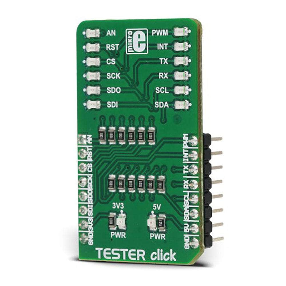
The Tester Click Board™ is used as a diagnostic tool on the mikroBUS socket. It contains an array of 2x6 LEDs, which signals the presence of the HIGH/LOW logic level on each pin, providing a visual feedback to the developer. Two additional LEDs indicate the presence of +3.3V and +5V on the mikroBUS power rails. This simple diagnostic tool can save hours of troubleshooting, saving the application developer from having to connect various complicated measurement instruments, only to test logic states on the specific mikroBUS pins.
Downloads
Each pin of the mikroBUS™ is routed to a red colored LED, which is protected by 1K resistor. This allows voltages up to VCC to be handled with no issues, providing a simple and clean solution for pin state testing. Once placed on the mikroBUS™ socket, no additional settings are required. There are no ICs or other active elements besides the LEDs. Its simplicity makes it very simple to use: as soon as it is connected, red and green power indication LEDs will signalize the presence of +3.3V and +5V on both the mikroBUS™ power rails. The rest of the LED array will be lit according to the state on the respective pin.
How Does The Tester Click board™ Work?
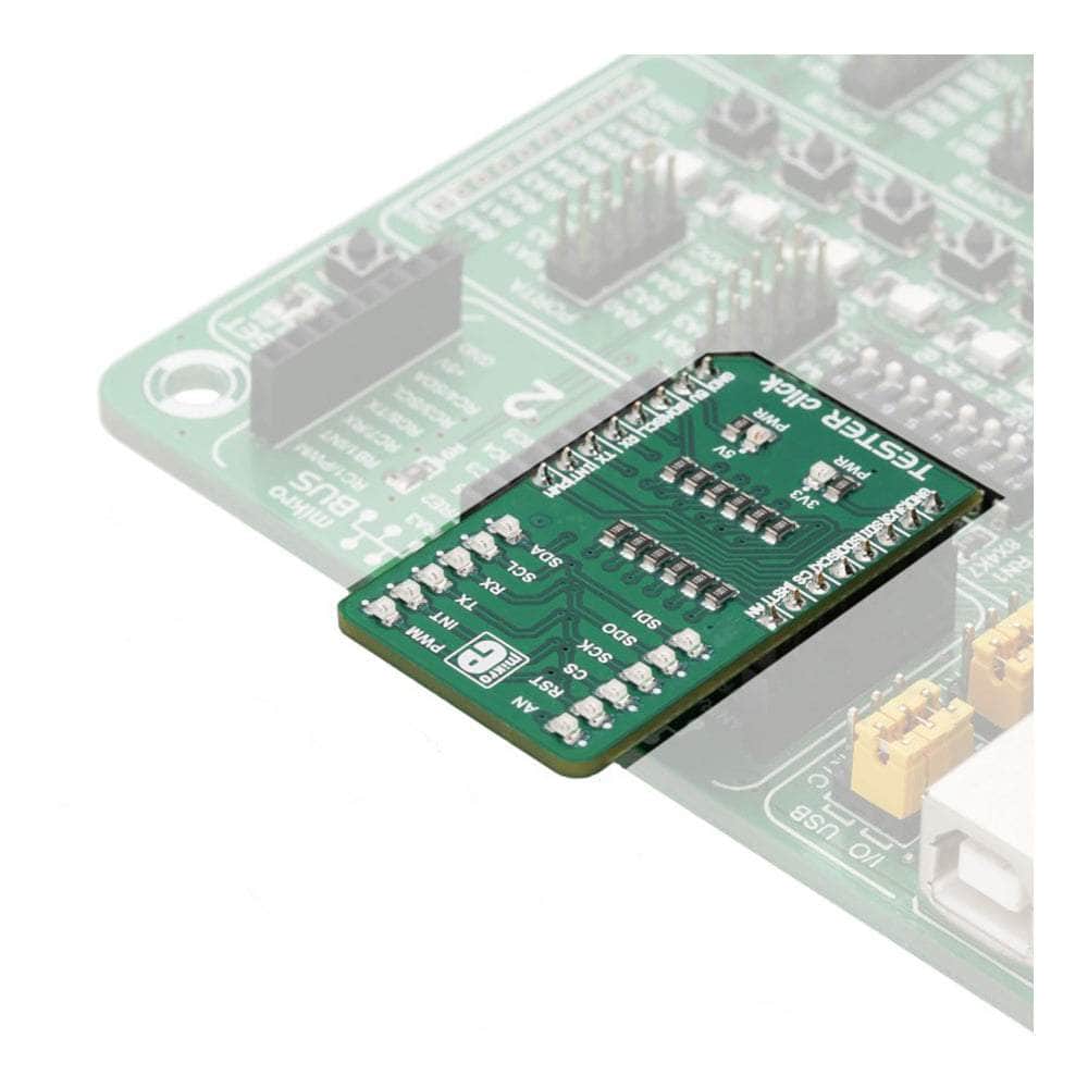
Development systems that utilize the mikroBUS™ socket, often require using of wire jumpers and/or connect the measuring equipment, routing the pin to another LED, or using some other workaround, in order to diagnose states on these pins. With the Tester Click board™, this task reduces to placing the Tester Click board™ onto the mikroBUS™ that needs to be tested, and LEDs will indicate if the state on the pin is HIGH or LOW with no additional hardware settings. This simplifies the troubleshooting greatly, potentially saving hours.
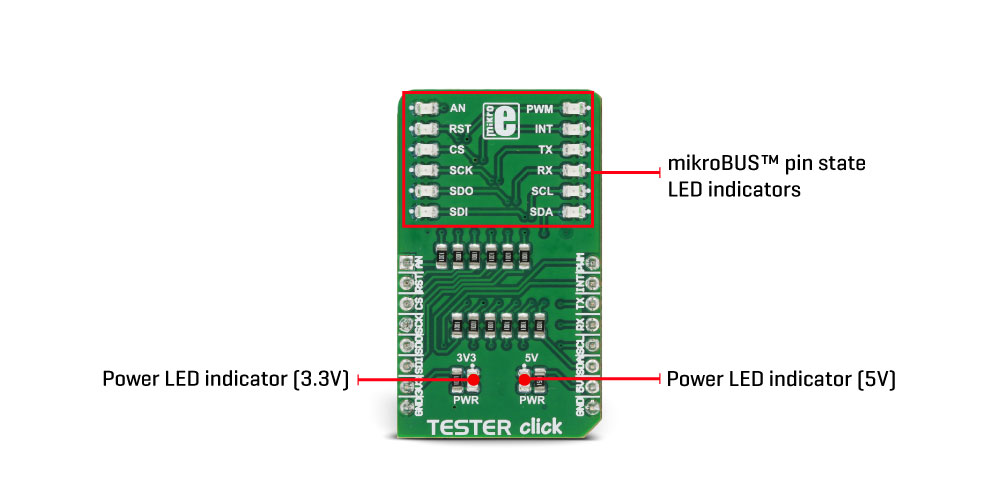
The Tester Click board™ itself consists of an array of 2x6 red colored LEDs, with their anodes connected each to the respective mikroBUS™ pin, via the 1K resistor. This resistor limits the current through the diode, allowing more than 5V to be handled with no problems. Each LED is clearly labelled the same as the pin it is connected to (e.g. PWM pin is routed to the LED labelled as PWM). Besides the 2x6 LED array, there are two additional LEDs, connected to the 3.3V and 5V power rails of the mikroBUS™, indicating presence of the VCC on both power rails. This simple design provides an easy, quick and simple tool to diagnose states of the mikroBUS™ pins.
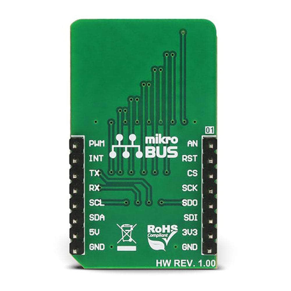
To fully understand how to use the Tester Click board™, its best to get familiar with the mikroBUS™ concept, first. The mikroBUS™ is a standardized connector, used on most of MikroElektronika development systems. Among other things, it strictly defines the pinout of the connector, offering all the most commonly used interfaces: SPI, I2C, UART, PWM, analog input pin (AN) and few additional GPIO pins (chip select pin - CS, interrupt pin - INT, and reset pin - RST). Also, mikroBUS™ includes two power rails: 3.3V and 5V. This allows development of many different Click boards™ which can be freely exchanged between many different systems and platforms, without any hardware reworks or changes - the appropriate pins will always be at the same place on every system equipped with the mikroBUS™ socket.
Therefore, the Tester Click board™ can be used to verify the signal integrity of the tested mikroBUS™, especially while developing customized systems that include one or more mikroBUS™ sockets, or when developing custom applications. More information about the mikroBUS™ standard and its requirements can be found on the official mikroBUS™ page.
SPECIFICATIONS
| Type | Proto |
| Applications | The Tester Click board™ is an ideal solution for testing and diagnostics of the mikroBUS™ socket pin states. |
| On-board modules | 2x6 red colored LEDs |
| Key Features | An array of 2x6 red LEDs with the protection resistors, two mode additional LEDs (red and green) for mikroBUS™ power indication, simple to use Click board™ diagnostic tool, no additional settings required |
| Interface | Analog,GPIO,I2C,PWM,SPI,UART |
| Compatibility | mikroBUS |
| Click board size | M (42.9 x 25.4 mm) |
| Input Voltage | 3.3V,5V |
PINOUT DIAGRAM
This table shows how the pinout of the Tester Click board™ corresponds to the pinout on the mikroBUS™ socket (the latter shown in the two middle columns).
| Notes | Pin | Pin | Notes | ||||
|---|---|---|---|---|---|---|---|
| Analog | AN | 1 | AN | PWM | 16 | PWM | PWM |
| Reset | RST | 2 | RST | INT | 15 | INT | Interrupt |
| Chip Select | CS | 3 | CS | RX | 14 | TX | UART Transmit |
| SPI Clock | SCK | 4 | SCK | TX | 13 | RX | UART Receive |
| SPI Data Out | SDO | 5 | MISO | SCL | 12 | SCL | I2C Clock |
| SPI Data In | SDI | 6 | MOSI | SDA | 11 | SDA | I2C Data |
| Power supply | 3.3V | 7 | 3.3V | 5V | 10 | 5V | Power supply |
| Ground | GND | 8 | GND | GND | 9 | GND | Ground |
| General Information | |
|---|---|
Part Number (SKU) |
MIKROE-3083
|
Manufacturer |
|
| Physical and Mechanical | |
Weight |
0.019 kg
|
| Other | |
EAN |
8606018713226
|
Frequently Asked Questions
Have a Question?
Be the first to ask a question about this.