

Mikroelektronika d.o.o.
RTD Click Board™
RTD Click Board™
SKU: MIKROE-2815
Couldn't load pickup availability


Overview
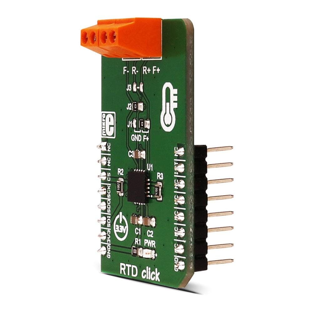
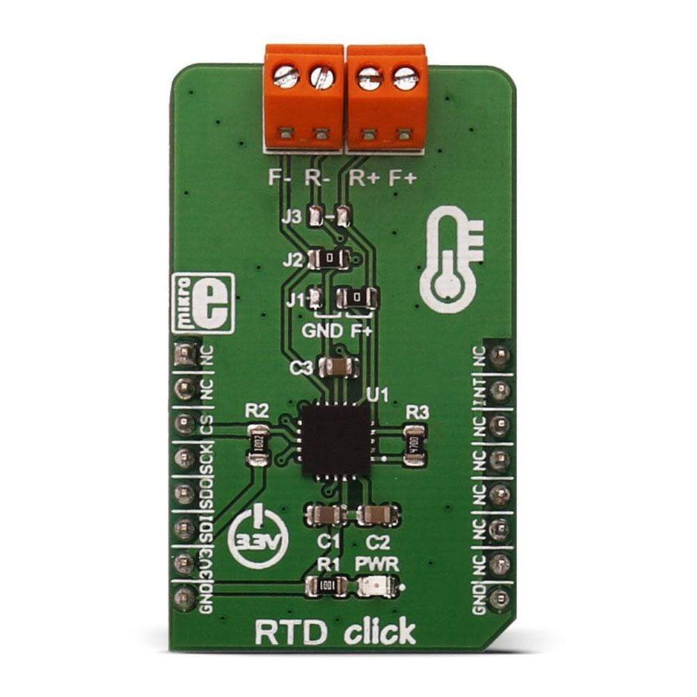
The RTD Click Board™ is based on MAX31865 resistance to digital converter from Maxim Integrated, optimised for platinum resistance temperature detectors, or RTD. The Click Board™ uses the PT100-type platinum probe for temperature measurement. There are four screw terminals on the board, so different PT100 probe types can be used with this design.
This RTD Click Board™ can work with 2, 3 or 4-wire PT100 probe types.
Downloads
The RTD Click Board™ is based on MAX31865 resistance to digital converter from Maxim Integrated, optimized for platinum resistance temperature detectors, or RTD. The click uses the PT100 type platinum probe for temperature measurement. There are four screw terminals on the board, so different PT100 probe types can be used with this design. This click board™ can work with 2, 3 or 4-wire PT100 probe types.
RTD probes are commonly used to measure a range of temperatures between −200°C and 500°C, but the exact value depends on the specific probes used. Features like the 15bit ADC resolution, input terminals overvoltage protection up to ±45V, fault detection, a fast response time of 21mS and the SPI interface, make the RTD click an ideal solution when it comes to the precise measuring of extremely high and low temperatures.
HOW DOES IT WORK?
RTD sensors are basically thermosensitive resistors – materials that change the resistance depending on their temperature. In this case, the resistor is a small strip of platinum with a resistance of 100Ω at 0°C - that is why it is called PT100. The RTD measurement is more stable and precise than with most NTC/PTC thermistors, so it is commonly used for measuring temperature in the laboratory and industrial processes.
Measurement probe is connected to the RTD Click Board™ by using the screw terminals, and it has wires that can be 1m long, which makes possible to measure high temperatures from a safe distance. To successfully measure small differences in the sensor resistance, the signal must be amplified. There is an input signal amplifier before the ADC converter, inside the MAX 31865 IC. Once amplified, the signal goes through the ADC converter and then, this value can be then read through the SPI interface on the mikroBUS™ socket. Since the temperature vs resistance curve of the platinum probes is not ideal, a compensating calculation is done with the functions, contained in the click library. The 15bit ADC can provide the resolution of ±0.3125°C, but the total accuracy of the RTD click is ±0.5°C.
The RTD click can work with several different variations of the RTD probes:
- The 2-wire probe connection can give acceptable results when the RTD is located close to the MAX31865. For the PT100 probes, the series resistance of 0.4Ω causes an error of approximately 1°C. Therefore, as the cable length increases, the error due to cable resistance can become excessive.
- The 3-wire probe connection is a compromise that uses one less conductor than the 4-wire solution. If the cable resistances are well matched, the error due to cable resistance is canceled.
- The 4-wire probe connection eliminates errors due to cable resistance by using separate force and sense leads.
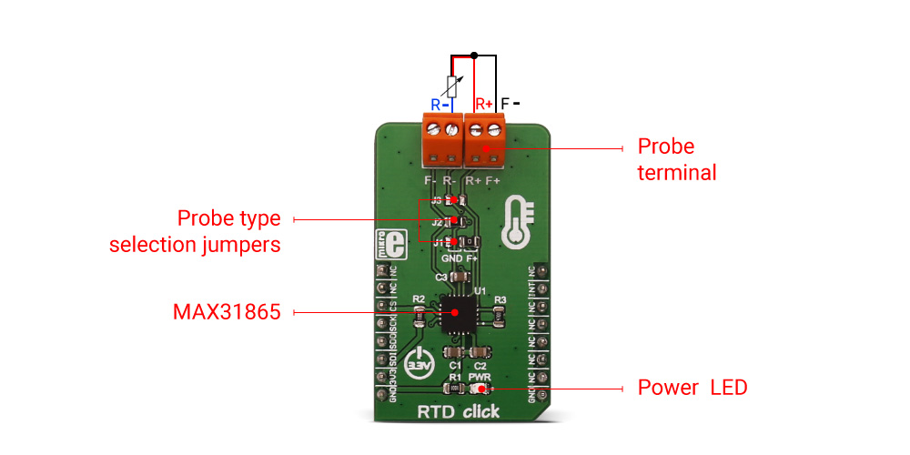
To select proper mode for the type of the connected probe, the SMD jumpers on the click board must be set to a proper position. The jumper settings can be found in the Onboard settings and indicators table, below.
DRDY - Data ready pin is used to signal a ready status to the MCU. This pin will go to a LOW logic state when there is a new conversion result is available in the data register. When a read operation of an RTD resistance data register occurs, DRDY goes to a HIGH logic level. It can be used to trigger an interrupt on the MCU so that the polling of the temperature registers can be avoided.
SPECIFICATIONS
| Type | Temperature & humidity |
| Applications | Measuring a wide range of temperatures in hard to reach places and in hazardous conditions. |
| On-board modules | The RTD Click Board™ uses Maxim Integrated MAX31865 15bit resistance to digital converter, optimized for platinum resistance temperature detectors (RTD) |
| Key Features | RTD click can be equipped 2, 3 or 4-wire PT100 RTD probe, measuring wide range of temperatures with the accuracy of ±0.5°C, ±45V overvoltage protection, fast measurement data processing of 21mS, DRDY pin for interrupt triggering... |
| Interface | GPIO,SPI |
| Compatibility | mikroBUS |
| Click board size | M (42.9 x 25.4 mm) |
| Input Voltage | 3.3V |
PINOUT DIAGRAM
This table shows how the pinout on the RTD Click Board™ corresponds to the pinout on the mikroBUS™ socket (the latter shown in the two middle columns).
| Notes | Pin | Pin | Notes | ||||
|---|---|---|---|---|---|---|---|
| NC | 1 | AN | PWM | 16 | NC | ||
| NC | 2 | RST | INT | 15 | DRDY | Data-Ready output | |
| SPI chip select | CS | 3 | CS | RX | 14 | NC | |
| SPI clock | SCK | 4 | SCK | TX | 13 | NC | |
| SPI slave data out | MISO | 5 | MISO | SCL | 12 | NC | |
| SPI slave data in | MOSI | 6 | MOSI | SDA | 11 | NC | |
| Power supply | 3.3V | 7 | 3.3V | 5V | 10 | NC | |
| Ground | GND | 8 | GND | GND | 9 | GND | Ground |
ONBOARD SETTINGS AND INDICATORS
| Label | Name | Default | Description |
|---|---|---|---|
| PWR | Power LED | - | Power LED indicates that the click is powered on |
| J1 | Jumper | Right | For 3-wire probe, connect to the RIGHT position. For 2 or 4-wire probe, connect to the LEFT position |
| J2 | Jumper | Soldered | Solder the 0Ω resistor when using the 2 or 3-wire probe, leave open for 4-wire probe |
| J3 | Jumper | NC | Solder the 0Ω resistor when using the 2-wire probe, leave open otherwise |
Note: RTD click is set to work with the 3-wire probe by default.
| General Information | |
|---|---|
Part Number (SKU) |
MIKROE-2815
|
Manufacturer |
|
| Physical and Mechanical | |
Weight |
0.019 kg
|
| Other | |
EAN |
8606018711888
|
Frequently Asked Questions
Have a Question?
Be the first to ask a question about this.