


Mikroelektronika d.o.o.
Fever Click Board™
Fever Click Board™
SKU: MIKROE-2554
Couldn't load pickup availability

Overview
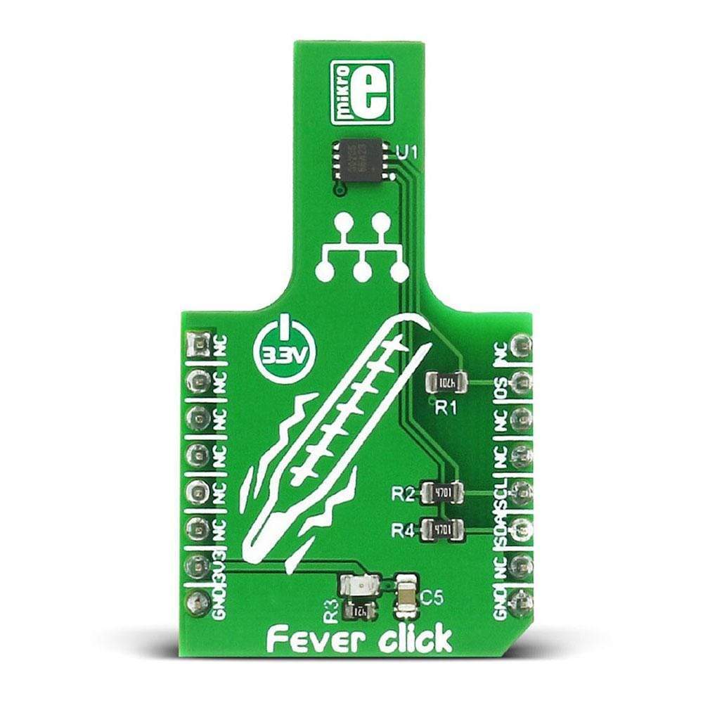
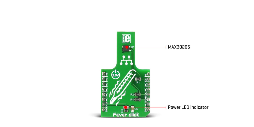
The Fever Click Board™ features a specially designed sensor, which is capable of accurate measurement of human body temperature. This Click Board™ uses the MAX30205 human body temperature sensor with an accuracy rating that complies with the clinical thermometry specifications of the ASTM E1112 standard. In addition, the sensor offers an open drain programmable interrupt output and uses the industry-standard I2C interface, enforced with the additional timeout feature, that prevents lockdown of the I2C bus.
The Fever Click Board™ includes some other features as well, such as the programmable interrupt pin polarity, improved accuracy in the range between 37.5 &Deg;C and 40.0 &Deg;C, low power consumption feature, and more.
Downloads
These features, along with the convenient design of the Fever Click Board™ keeping the sensor itself away from any PCB thermal sources, allow simple use of the device and easy development of various applications. Fever click is a perfect solution for development of health related applications, especially when combined with other health-related Click boards™. It can be used either for monitoring of the body temperature, or it can be simply set to alert about "fever – no fever" states: condition of the human body when the temperature is greater than 37.5℃, is considered a fever.
How Does The Fever Click Board™Work?
The main active component of the Fever Click Board™ is the MAX30205, an integrated human body temperature sensor from Analog Devices. This sensor is specifically designed to be used as the human body temperature sensor, featuring accuracy that complies with the clinical thermometry specifications of the ASTM E1112 standard. The sensor is most accurate in the region of 37℃ to 39℃, with the least mean error in this area. The overall accuracy of the sensor is greatly affected by the temperature of the PCB itself since the sensor measures its die temperature. Therefore, the PCB of the Fever click has such shape that the sensor is physically moved away from any other thermal source, and the PCB under the sensor is small enough, reducing the overall thermal inertia. The temperature is sampled with the 16-bit sigma delta A/D converter, and thermal data is delivered via the I2C bus, with 0.00390625 °C per LSB.
The Fever Click Board™ exposes the I2C interface and the OS pin on the mikroBUS™, making it very simple to use. I2C pins are routed to the appropriate I2C pins of the mikroBUS™, equipped with the required pull-up resistors. The OS pin is also an open drain output, which can work in two modes: it can be used as the interrupt, or as the thermostat/comparator.
When operating as an interrupt, the OS pin will be asserted once the programmed threshold temperature is exceeded (TOS register). It won't be de-asserted until any of the registers is read by the host MCU. Again, it will be asserted next time the threshold is exceeded, reset when a register is read, and so on.
When working as the comparator/thermostat, the OS pin will be asserted once the programmed thermal threshold has been exceeded (TOS), but it will be de-asserted when the temperature drops below the hysteresis, set in the THYST register. The nature of this mode is similar to an operation of a thermostat, so this mode can be used to initiate cooling fans, automatized air conditioning, and so forth.
The OS pin mode is determined by the state of the CMP/INT bit in the config register. A logic 0 will set the comparator mode. The polarity of the OS can also be programmed, and it is determined by the OS POLARITY bit of the config register. A special fault counter is used in order to avoid erratic behavior near the threshold range. The number of faults (conditions when the temperature exceeds threshold values) is determined by two bits in the configuration register. The OS pin will be asserted only when the programmed number of faults is reached, effectively acting as a filter, preventing false triggering situations. OS pin is routed to the mikroBUS™ INT pin, labelled as OS.
The power consumption is an important characteristic when building embedded applications. Therefore, this sensor allows ONE SHOT mode to be used, reducing the overall power consumption. This allows the device to operate while staying in the SHUTDOWN mode. Writing logic 1 to an appropriate bit of the configuration register will wake up the device from the SHUTDOWN mode, perform one temperature conversion, and revert the sensor back to SHUTDOWN mode. This mode is very useful if the application allows less measurement samples to be taken per time interval.
As mentioned above, the I2C bus has the timeout feature. A logic 0 will enable the timeout feature, preventing the SDA pin to stay at LOW logic level for more than 50 ms. In addition, the I2C bus has the lowpass filters applied to its pins, preventing excessive EMI to affect the communication. Combined with the careful layout of the PCB, this helps reducing the digital noise sensitivity of the Click board™. This makes for a robust I2C interface, immune to interferences which is able to work even in reasonably noisy environments.
SPECIFICATIONS
| Type | Temperature & humidity |
| Applications | The Fever Click Board™ is a perfect solution for development of health-related applications. It can be used either for monitoring of the body temperature, or it can be simply set to alert about ""fever – no fever"" states. |
| On-board modules | MAX30205, an integrated human body temperature sensor, from Maxim Integrated |
| Key Features | Specially designed PCB, accurate thermal sensor, compliant with the ASTM E1112 standard, dual mode interrupt output with programmable polarity, improved accuracy in the range of 37.5 ℃ to 40.0 ℃, low power consumption, and more. |
| Interface | I2C |
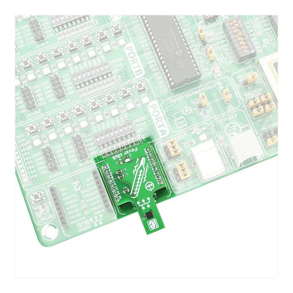
| Compatibility | mikroBUS |
| Click board size | M (42.9 x 25.4 mm) |
| Input Voltage | 3.3V |
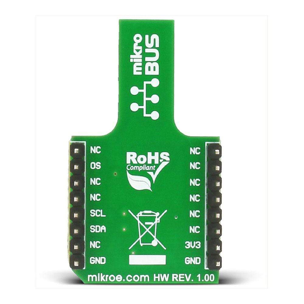
PINOUT DIAGRAM
This table shows how the pinout of the Fever Click Board™ corresponds to the pinout on the mikroBUS™ socket (the latter shown in the two middle columns).
| Notes | Pin | Pin | Notes | ||||
|---|---|---|---|---|---|---|---|
| NC | 1 | AN | PWM | 16 | NC | ||
| NC | 2 | RST | INT | 15 | OS | Interrupt/Comparator | |
| NC | 3 | CS | TX | 14 | NC | ||
| NC | 4 | SCK | RX | 13 | NC | ||
| NC | 5 | MISO | SCL | 12 | SCL | I2C | |
| NC | 6 | MOSI | SDA | 11 | SDA | I2C | |
| Power supply | +3.3V | 7 | 3.3V | 5V | 10 | NC | |
| Ground | GND | 8 | GND | GND | 9 | GND | Ground |
FEVER CLICK SPECIFICATION
| Description | Min | Typ | Max | Unit |
|---|---|---|---|---|
| Conversion time | 44 | 50 | ms | |
| Thermal accuracy (depends on the temperature range) | 5 | mA | ||
| Resolution | 0.00390625 | °C/LSB |
ONBOARD JUMPERS AND SETTINGS
| Label | Name | Default | Description |
|---|---|---|---|
| LD1 | PWR | - | Power LED indicator |
| General Information | |
|---|---|
Part Number (SKU) |
MIKROE-2554
|
Manufacturer |
|
| Physical and Mechanical | |
Weight |
0.017 kg
|
| Other | |
EAN |
8606018710201
|
Frequently Asked Questions
Have a Question?
Be the first to ask a question about this.