


Mikroelektronika d.o.o.
USB to I2C 2 Click Board™
USB to I2C 2 Click Board™
SKU: MIKROE-5065
Couldn't load pickup availability


Overview
The USB to I2C 2 Click Board™ is a compact add-on board that contains a general-purpose USB to I2C serial interface. This board features the FT201X, a full-speed USB to I2C protocol converter from FTDI. The FT201X converts USB2.0 full-speed to an I2C serial interface capable of operating up to 3.4MBit/s, with low power consumption (typical 8mA). The entire USB protocol is handled on the chip itself, where no USB-specific firmware programming is required. It also has a fully-integrated 2048 byte Multi-Time-Programmable (MTP) memory for storing device descriptors and CBUS I/O user-desirable configuration. This Click board™ includes the complete FT-X series feature set and enables USB to be added into a system design quickly and easily over an I2C interface.
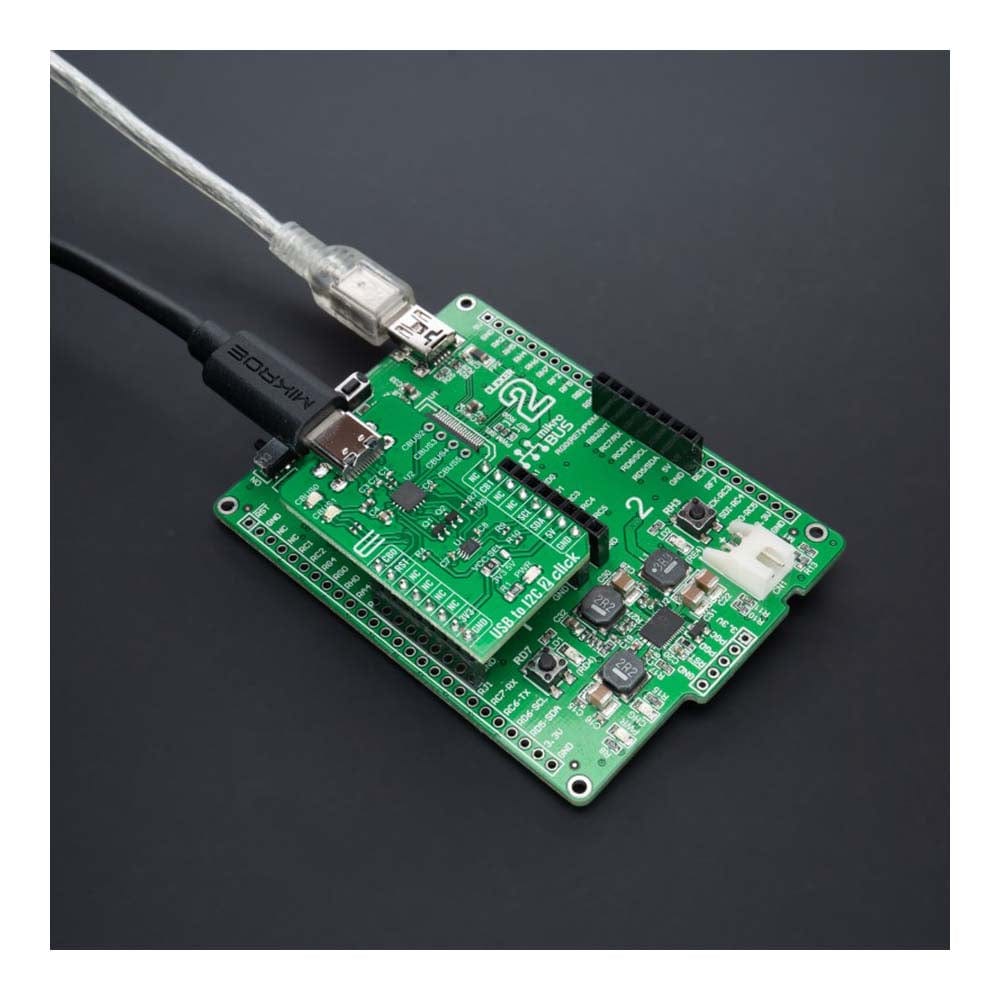
The USB to I2C 2 Click Board™ is supported by a mikroSDK compliant library, which includes functions that simplify software development. This Click board™ comes as a fully tested product, ready to be used on a system equipped with the mikroBUS™ socket.
Downloads
How Does The USB to I2C 2 Click Board™ Work?
The USB to I2C 2 Click Board™ is based on the FT201X, a USB to I2C interface device which simplifies USB implementations from FTDI. The FT201X is USB 2.0 full-speed compatible and handles the entire USB protocol by itself; no USB-specific firmware programming is required. It fully integrates 2048 byte Multi-Time-Programmable (MTP) memory for storing device descriptors and CBUS I/O user-desirable configuration and clock generation with no external crystal required plus optional clock output selection enabling a glue-less interface to external MCU or FPGA.
The USB to I2C 2 Click Board™ communicates with MCU using the standard I2C 2-Wire interface to read data and configure settings, supporting Standard Mode operation with a clock frequency of 100kHz and Fast Mode up to 400kHz. Since the FT201X for operation requires a 5V only, this Click board™ also features the PCA9306 voltage-level translator from Texas Instruments. The I2C interface bus lines are routed to the dual bidirectional voltage-level translator, allowing this Click board™ to work with both 3.3V and 5V MCUs properly.
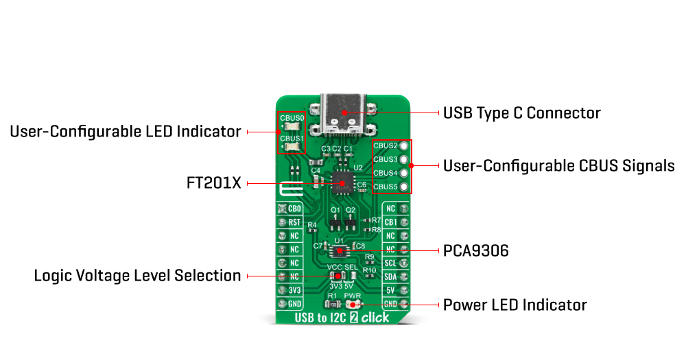
The FT201X also contains an embedded fully integrated MTP memory used to specify the functionality of the Control Bus (CBUS) pins, the current drive on each signal pin, the current limit for the USB bus, and the descriptors of the device. There are six configurable CBUS I/O pins, two of which are routed on AN and INT pins of the mikroBUS™ socket, marked as CB0 and CB1, alongside the two blue LED indicators labelled as CBUS0 and CBUS1 used for optional user-configurable visual indication.
The other four CBUS pins can be found on the onboard CBUS header, and be used as user-configurable CBUS signals. A wide range and the way of using these pins can be found in the attached datasheet. This board also uses an active-low reset signal routed on the RST pin of the mikroBUS™ socket, which provides a reliable Power-On reset to the device's internal circuitry at Power-Up.
The USB to I2C 2 Click Board™ can operate with both 3.3V and 5V logic voltage levels selected via the VCC SEL jumper. This way, it is allowed for both 3.3V and 5V capable MCUs to use the communication lines properly. However, the Click board™ comes equipped with a library that contains easy-to-use functions and an example code that can be used, as a reference, for further development.
SPECIFICATIONS
| Type | USB |
| Applications | The USB to I2C 2 Click Board™ includes the complete FT-X series feature set and enables USB to be added into a system design quickly and easily over an I2C interface |
| On-board modules | FT201X - full-speed USB to I2C protocol converter from FTDI |
| Key Features | USB 2.0 full-speed compatible, entire USB protocol handled on the chip, integrated 2048 byte MTP memory, configurable CBUS I/O pins, and more |
| Interface | I2C,USB |
| Compatibility | mikroBUS |
| Click board size | M (42.9 x 25.4 mm) |
| Input Voltage | 3.3V or 5V |
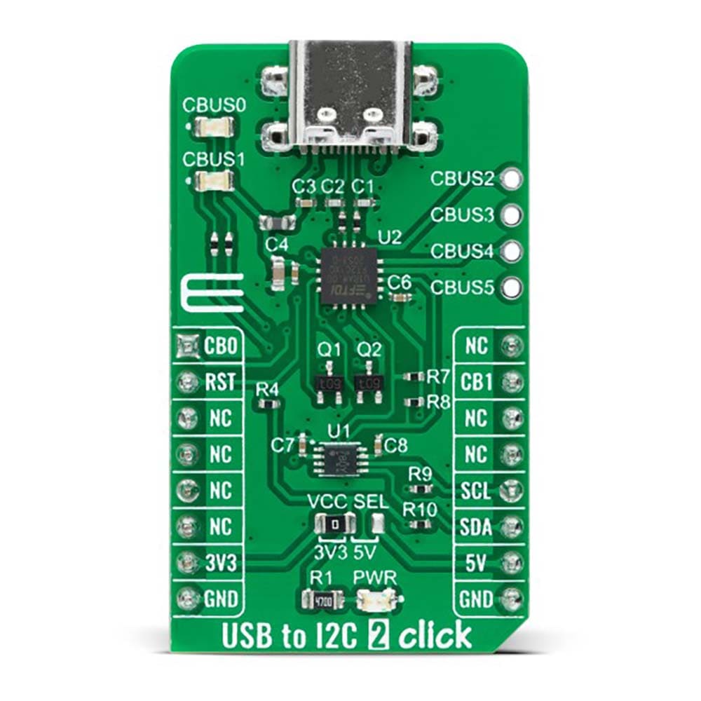
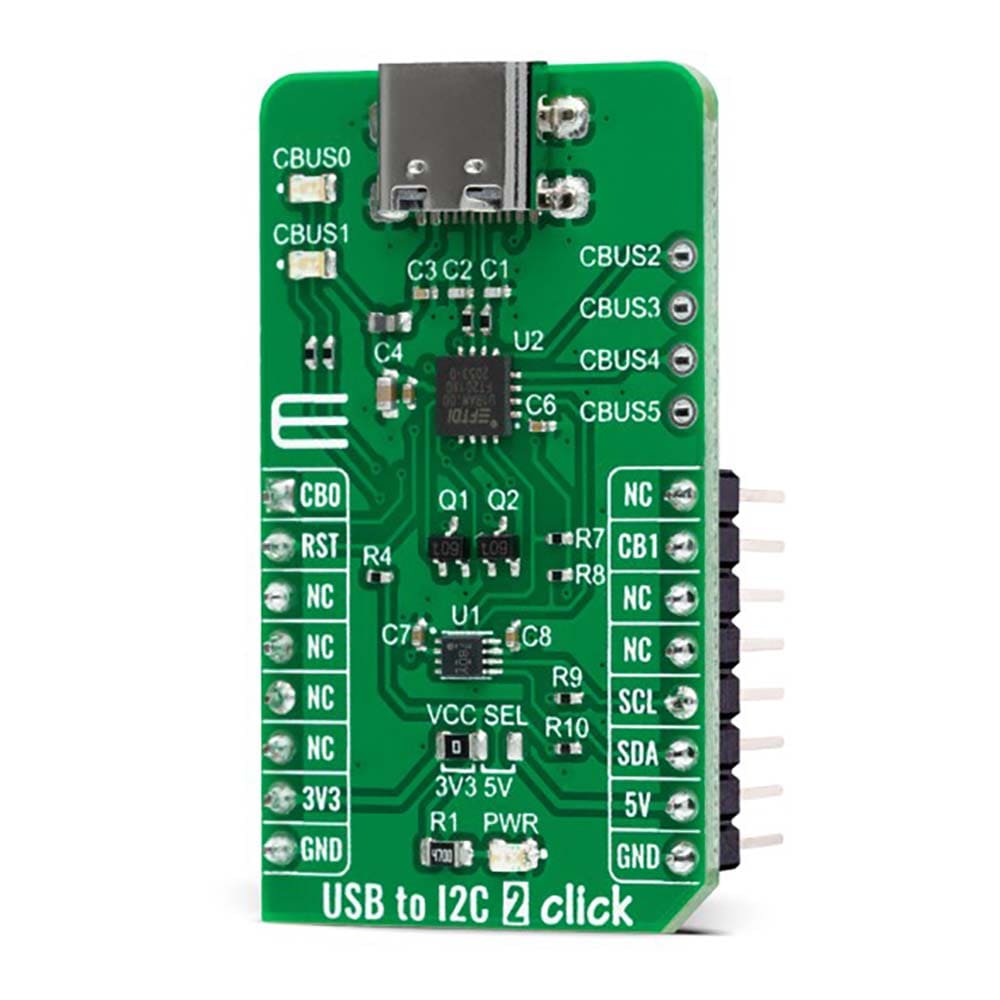
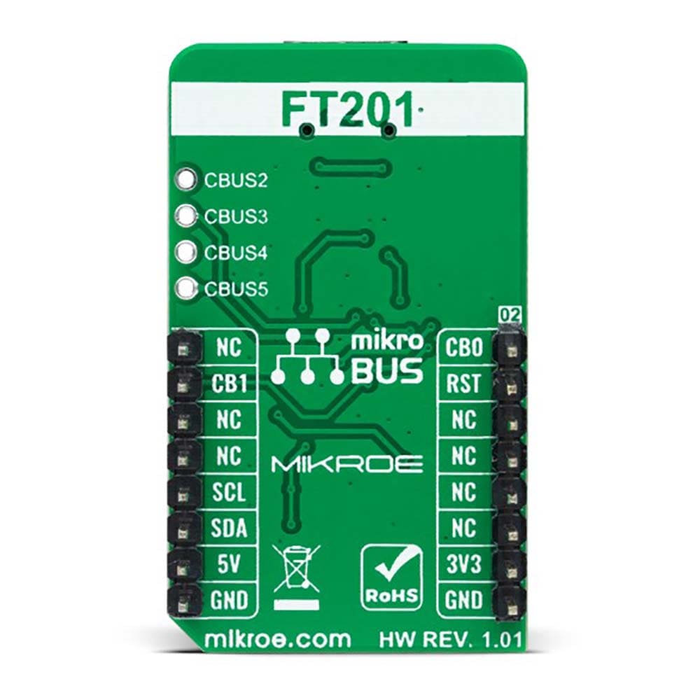
PINOUT DIAGRAM
This table shows how the pinout of the USB to I2C 2 Click Board™ corresponds to the pinout on the mikroBUS™ socket (the latter shown in the two middle columns).
| Notes | Pin | Pin | Notes | ||||
|---|---|---|---|---|---|---|---|
| Control Pin 0 | CB0 | 1 | AN | PWM | 16 | NC | |
| Reset | RST | 2 | RST | INT | 15 | CB1 | Control Pin 1 |
| NC | 3 | CS | RX | 14 | NC | ||
| NC | 4 | SCK | TX | 13 | NC | ||
| NC | 5 | MISO | SCL | 12 | SCL | I2C Clock | |
| NC | 6 | MOSI | SDA | 11 | SDA | I2C Data | |
| Power Supply | 3.3V | 7 | 3.3V | 5V | 10 | 5V | Power Supply |
| Ground | GND | 8 | GND | GND | 9 | GND | Ground |
ONBOARD SETTINGS AND INDICATORS
| Label | Name | Default | Description |
|---|---|---|---|
| LD1 | PWR | - | Power LED Indicator |
| LD2-LD3 | CBUSO-CBUS1 | - | User-Configurable LED Indicators |
| JP1 | VCC SEL | Left | Logic Level Voltage Selection 3V3/5V: Left position 3V3, Right position 5V |
| J1 | - | Unpopulated | User-Configurable CBUS Pins Header |
USB TO I2C 2 CLICK ELECTRICAL SPECIFICATIONS
| Description | Min | Typ | Max | Unit |
|---|---|---|---|---|
| Supply Voltage | 3.3 | - | 5 | V |
| Data Rate | - | - | 12 | Mbit/s |
| CBUS Pins Output Current | 4 | - | 16 | mA |
| Operating Temperature Range | -40 | +25 | +85 | °C |
| General Information | |
|---|---|
Part Number (SKU) |
MIKROE-5065
|
Manufacturer |
|
| Physical and Mechanical | |
Weight |
0.02 kg
|
| Other | |
EAN |
8606027389221
|
Frequently Asked Questions
Have a Question?
Be the first to ask a question about this.