


Mikroelektronika d.o.o.
Binho Nova Click Board™
Binho Nova Click Board™
SKU: MIKROE-4439
Couldn't load pickup availability


Key Features
Overview
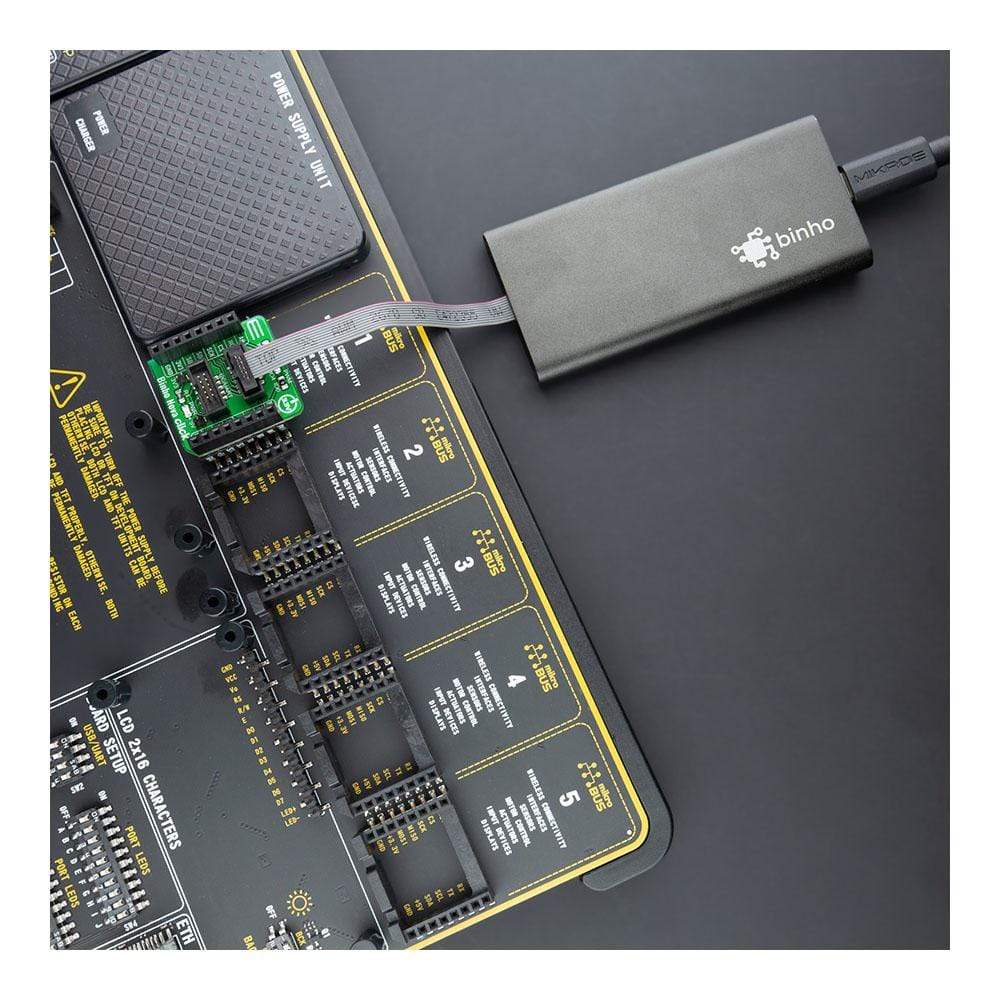
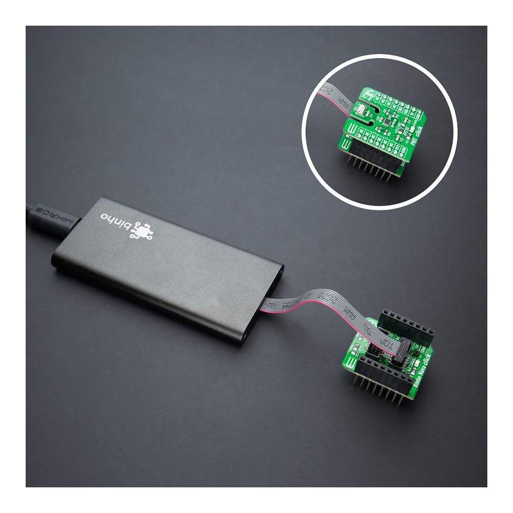
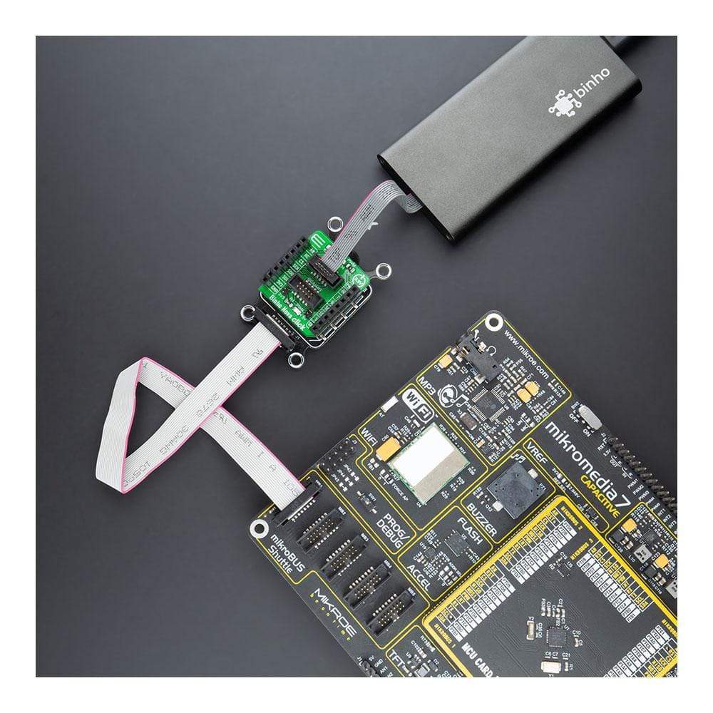
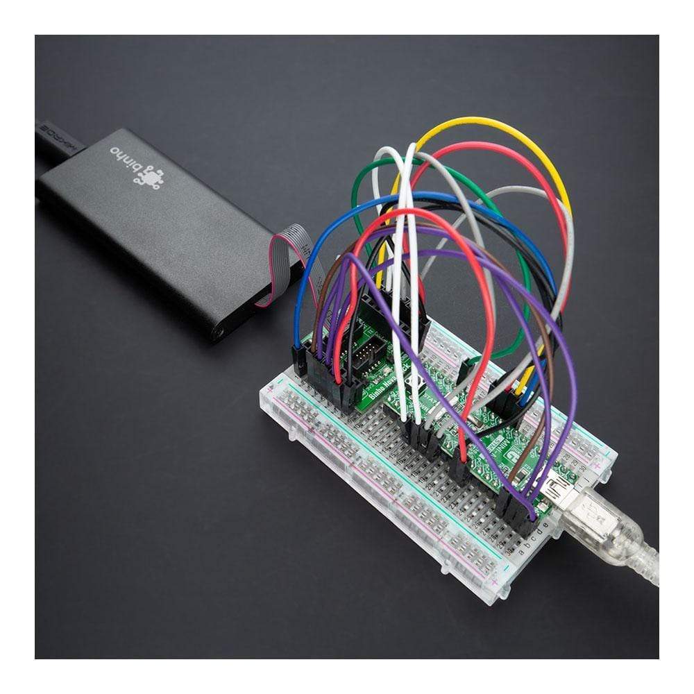
The Binho Nova Click Board™ is an adapter that can be used as a multi-protocol adapter. This board features two female 1.27mm 2x5 connectors suitable for connecting the Binho Nova Multi-Protocol USB Host Adapter, depending on the desired interface. This Click Board™ is designed for ultimate flexibility and allows the use of this adapter with different communication protocols, such as I2C, SPI, or UART. It features five signal pins, which can be used as Digital Input/Output, PWM Output, Digital Interrupt, or Analog Input/Output. Along with these connectors, it also features two power jumpers that can be used to supply the host from the Binho Nova. This Click Board™ is suitable for manual testing during firmware development, debugging, and automating hardware testing and validation.
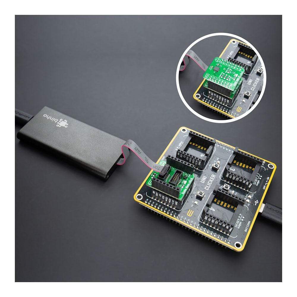
NOTE: The Binho Nova Click Board™ comes with stacking headers that allow you to easily combine it with other Click boards™ by using just one mikroBUS™ socket.
Downloads
How Does The Binho Nova Click Board™ work?
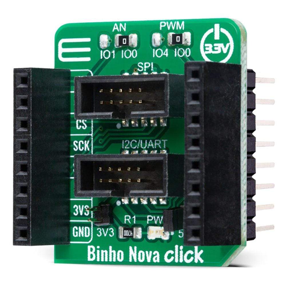
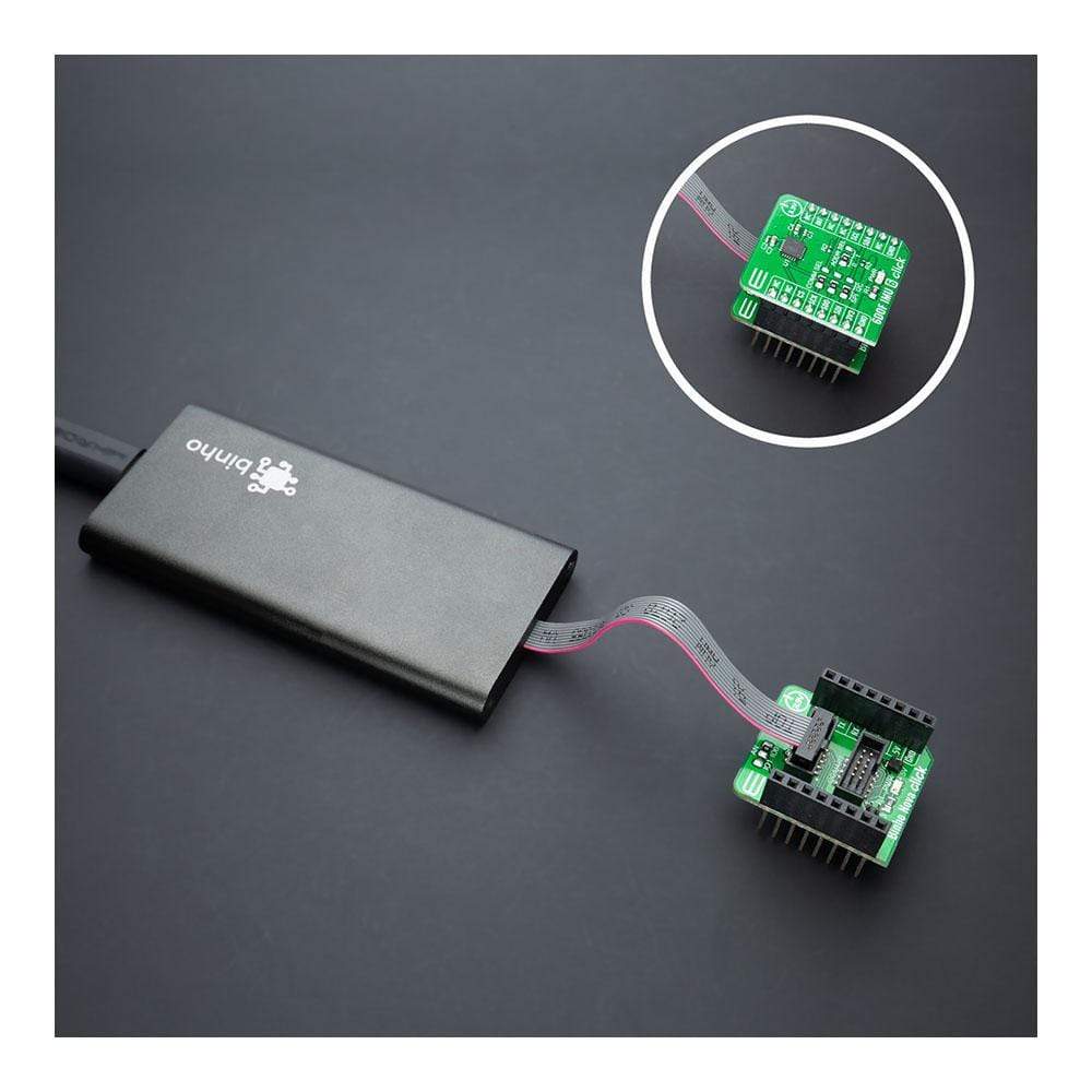
The Binho Nova Click Board™ was designed for ultimate flexibility with multiple ways to control and interact with it. It features two female 1.27mm 2x5 connectors suitable for connecting the Binho Nova Multi-Protocol USB Host Adapter depending on the desired interface. The connected Binho Nova Adapter is powered by its USB connection to the host PC and provides downstream power to the Binho Nova Click board™. Additionally, two power jumpers labelled as 3V3 and 5V are used to supply the host from the connected Binho Nova Adapter. It represents a perfect solution for manual testing during firmware development and debugging, automating hardware testing, and validation.

Binho Nova USB Host Adapter has 3 modes of operation: Master, Slave, and Monitor/Debug. By default, it communicates as a Master device, while the Slave device support is coming soon and will be made available to all existing devices via a firmware update. Thanks to the stacking headers that this Click board™ has, there is the possibility of connecting any Click board™ with the Binho Nova Click board™. In this way, it is possible to use the USB Host Adapter in a Mode that would monitor when the MCU communicates with additional Click while "sniffing" communications and protocols.
The Binho Nova Click Board™ can establish communication with MCU using several different communication protocols. It can serve as an SPI bus controlled device, with a frequency between 500kHz and 12MHz and with all 4 SPI modes are supported, or can serve as an I2C bus controlled device that supports clock frequencies from 100kHz up to 3.4MHz that covers all common operational modes (Standard, Full-Speed, Fast, and High-Speed). In addition to using these two communications, it also supports communication as a UART pass-through, with a maximum baud rate of 1.000.000bps for the data transfer.
Some Binho Nova connector pins can be assigned to other, related or unrelated, purposes such as GPIO, interrupt, PWM signals, or analogue input/outputs. In that manner, two onboard jumpers, labelled as AN and PWM, are used to designate which pin from the Binho Nova connector is connected to the AN pin or PWM on the mikroBUS ™ socket. The default state of AN jumper represents enabled SPI communication while optionally provides the ability to use ADC/DAC, where SPI is not active. On the other hand, with the PWM jumper, the default state is enabled I2C and UART communication, while the optional state provides PWM where the UART is disabled.
The Binho Nova Click Board™ features two enable jumpers used to supply the host from the Binho USB Host Adapter. The presence of an active power supply is visually detected by a green LED diode labelled as PWR. In the case of using the Binho USB Host Adapter in Slave or Monitoring/Debug Mode, these headers need to be removed. Only when Master Mode is used and is necessary to power the host headers should be left on the Click board™.
SPECIFICATIONS
| Type | Adapter |
| Applications | Can be used for manual testing during firmware development and debugging and automating hardware testing and validation. |
| On-board modules | This board features two female 1.27mm 2x5 connectors suitable for connecting the Binho Nova Multi-Protocol USB Host Adapter depending on the desired interface, in association with stacking headers that allow you to easily combine it with other Click boards™ by using just one mikroBUS™ socket. |
| Key Features | Multi-protocol adapter, support for SPI I2C and UART interface, configurable pins (GPIO, Interrupt, PWM), ideal for testing and validation, and more. |
| Interface | PWM,UART,Analog,GPIO,I2C,SPI |
| Compatibility | mikroBUS |
| Click board size | S (28.6 x 25.4 mm) |
| Input Voltage | 5V, 3.3V,External |
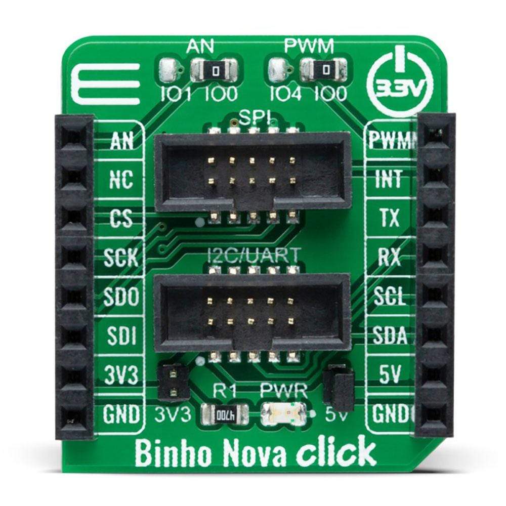
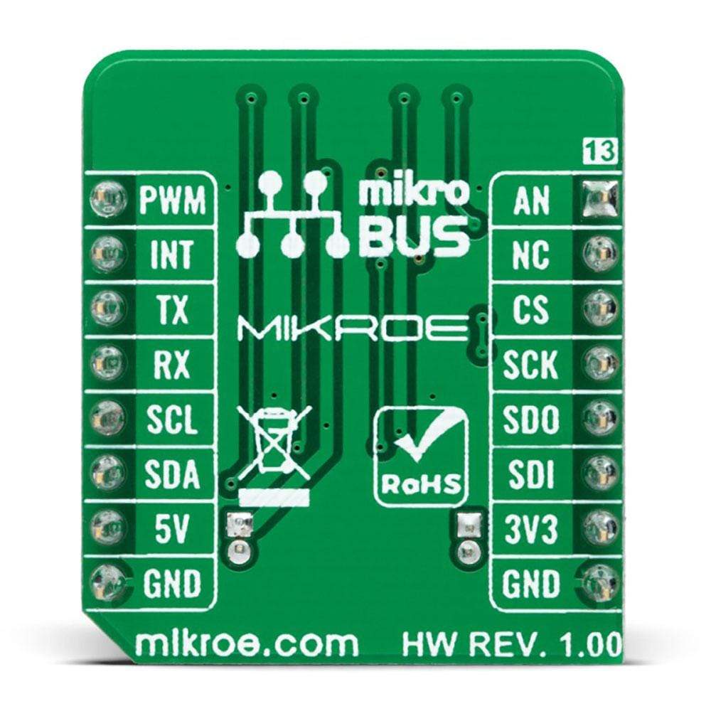
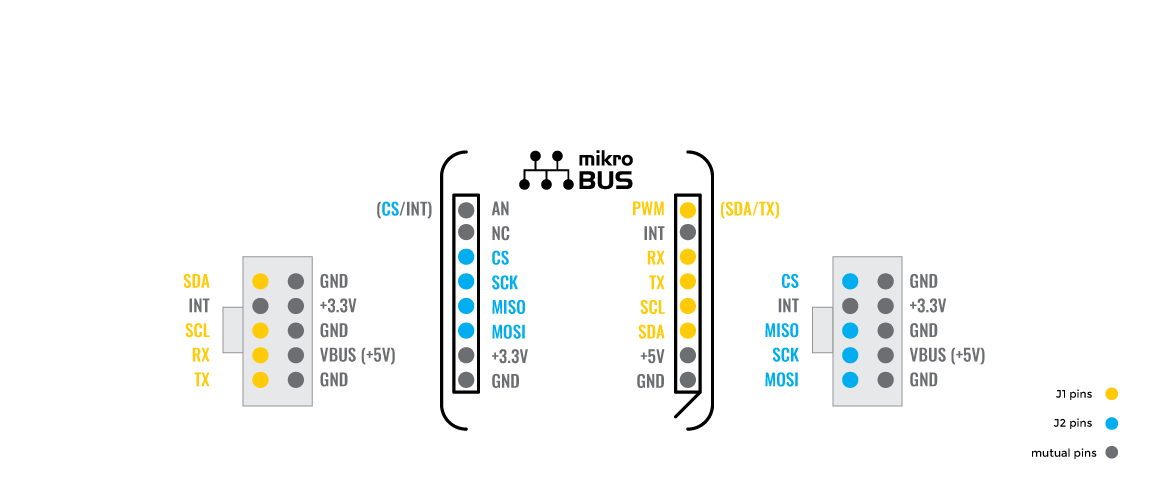
PINOUT DIAGRAM
This table shows how the pinout on the Binho Nova Click Board™ corresponds to the pinout on the mikroBUS™ socket (the latter shown in the two middle columns).
| Notes | Pin | Pin | Notes | ||||
|---|---|---|---|---|---|---|---|
| CS/INT Selection | AN | 1 | AN | PWM | 16 | PWM | SDA/TX Selection |
| NC | 2 | RST | INT | 15 | INT | Interrupt | |
| SPI Chip Select | CS | 3 | CS | RX | 14 | TX | UART TX |
| SPI Clock | SCK | 4 | SCK | TX | 13 | RX | UART RX |
| SPI Data OUT | SDO | 5 | MISO | SCL | 12 | SCL | I2C Clock |
| SPI Data IN | SDI | 6 | MOSI | SDA | 11 | SDA | I2C Data |
| Power Supply | 3.3V | 7 | 3.3V | 5V | 10 | 5V | Power Supply |
| Ground | GND | 8 | GND | GND | 9 | GND | Ground |
ONBOARD SETTINGS AND INDICATORS
| Label | Name | Default | Description |
|---|---|---|---|
| LD1 | PWR | - | Power LED Indicator |
| JP1 | PWR | Left | Binho Nova I/O Signal Selection IO1/IO0: Left position IO1, Right position IO0 |
| JP2 | AN | Left | Binho Nova I/O Signal Selection IO4/IO0: Left position IO4, Right position IO0 |
| J1 | SPI | Populated | Connector for SPI/Analog Interface |
| J2 | I2C/UART | Populated | Connector for I2C/UART/PWM Interface |
| J3 | 3V3 | Unpopulated | Supply Enable Jumpers from Binho Nova Host USB Adapter |
| J4 | 5V | Unpopulated | Supply Enable Jumpers from Binho Nova Host USB Adapter |
BINHO NOVA CLICK ELECTRICAL SPECIFICATIONS
| Description | Min | Typ | Max | Unit |
|---|---|---|---|---|
| Supply Voltage | 3.3 | - | 5 | V |
| Binho USB Host Adapter Output Current | - | - | 100 | mA |
| Operating Temperature Range | 0 | +25 | +80 | °C |
| General Information | |
|---|---|
Part Number (SKU) |
MIKROE-4439
|
Manufacturer |
|
| Physical and Mechanical | |
Weight |
0.018 kg
|
| Other | |
EAN |
8606027381263
|
Frequently Asked Questions
Have a Question?
Be the first to ask a question about this.