


Mikroelektronika d.o.o.
M-Bus Slave Click Board™
M-Bus Slave Click Board™
SKU: MIKROE-4137
Couldn't load pickup availability


Overview
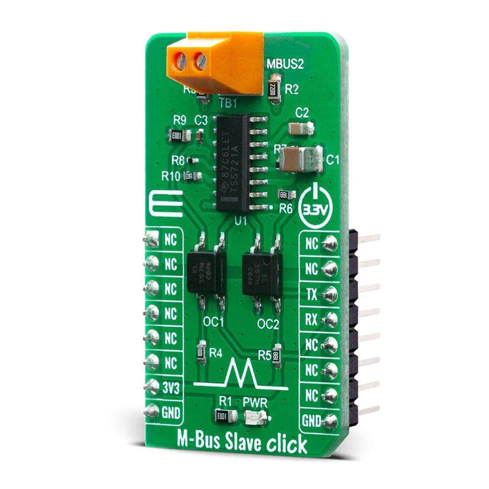
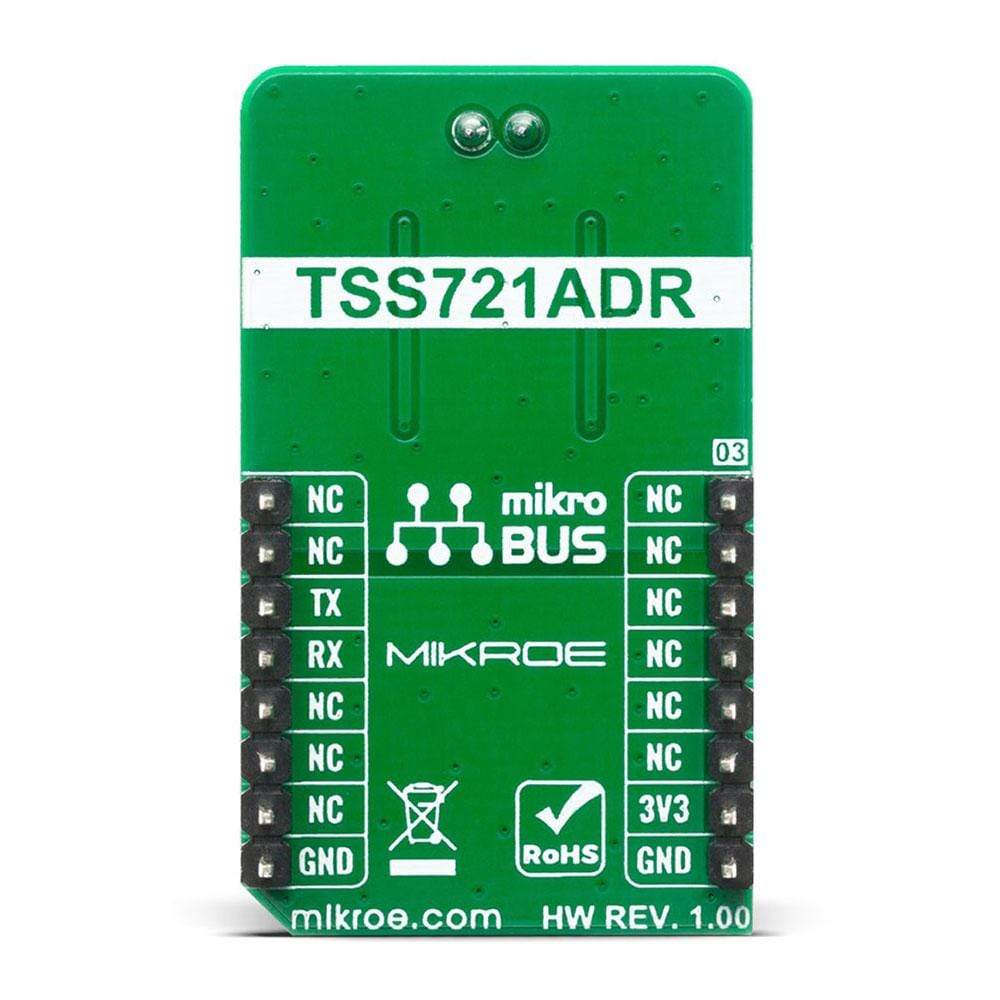
The M-Bus Slave Click Board™ is equipped with the TSS721A, a single chip transceiver developed by Texas Instruments for Meter-Bus applications according to EN1434-3 standard. The connection to the bus is polarity independent and serves as a slave node in the system.
The M-Bus Slave Click Board™ has full galvanic isolation with optocouplers to improve the reliability of the whole circuit. The circuit is supplied by the master via the bus. Therefore, this circuit offers no additional load for the slave battery. The TSS721A has a power-fail function integrated within. This solution is perfect for a plethora of applications like remote reading of gas, water, heat or electricity, or other types of consumption meters.
Downloads
How Does The M-Bus Click Board™ Work?
M-Bus is a bus system used for the remote reading of gas, water, heat, electricity, etc. It also supports various sensors and actuators. This is a cost-optimized bus for the transfer of energy consumption data since it is made for communication on only two wires. M-Bus can be used in the industry, but also, it's convenient to be used in private households. By the standard, M-Bus master can read up to 250 slave devices. They can be meters, water, electrical, or gas meters. You can also use M-bus in applications like alarm systems, flexible illumination installations, heating control, etc. It can monitor different consumption meters, and it can monitor any leakage.
.jpg)
One of the biggest advantages of M-Bus are:
- All data reading is accomplished remotely.
- It is a very simple protocol – it uses only two wires, and it uses a power supply from the users which are connected to the wire.
- Reading errors are minimal. Also, reading is very fast. Further processing is very easy since the received data is presented in a machine-readable form.
- There are no special cables – you can use a telephone cable. With that one cable, you can attach all the meters in the housing with all the meters individually addressable. This way you can have control over each consumption meter while using only one connection cable.
The M-Bus Slave Click Board™ uses the TSS721A, a single chip transceiver developed for Meter-Bus standard (EN1434-3) applications. The connection to the bus is polarity independent and serves as a slave node in the system. The M-Bus Slave Click Board™ has full galvanic isolation with optocouplers to improve the reliability of the whole circuit. The circuit is supplied by the master via the bus. The benefit of the TSS721A in M-Bus slaves is the reduction of the number of components needed, and therefore the cost of slaves. Apart from the transmission and reception of data by the M-Bus specification, this IC also provides translation from and to the operating voltage of the microprocessor to which it is connected, to be able to communicate with it. The communication can take place at baud rates from 300 to 9600 Baud. Additional features include integrated protection against reversed polarity, a constant 3.3V power supply for the microprocessor, and the prompt indication of failure of the bus voltage.
SPECIFICATIONS
| Type | RS232 |
| Applications | Remote sensor reading, remote control over M-Bus |
| On-board modules | The M-Bus Slave Click Board™ uses the TSS721A IC, a single chip transceiver developed for Meter-Bus standard, from Texas Instruments |
| Key Features | Galvanically isolated, Slave node |
| Interface | UART |
| Compatibility | mikroBUS |
| Click board size | M (42.9 x 25.4 mm) |
| Input Voltage | 3.3V |
PINOUT DIAGRAM
This table shows how the pinout on the M-Bus Slave Click Board™ corresponds to the pinout on the mikroBUS™ socket (the latter shown in the two middle columns).
| Notes | Pin | Pin | Notes | ||||
|---|---|---|---|---|---|---|---|
| NC | 1 | AN | PWM | 16 | NC | ||
| NC | 2 | RST | INT | 15 | NC | ||
| NC | 3 | CS | RX | 14 | TX | UART TX | |
| NC | 4 | SCK | TX | 13 | RX | UART RX | |
| NC | 5 | MISO | SCL | 12 | NC | ||
| NC | 6 | MOSI | SDA | 11 | NC | ||
| Power Supply | 3.3V | 7 | 3.3V | 5V | 10 | NC | |
| Ground | GND | 8 | GND | GND | 9 | GND | Ground |
ONBOARD SETTINGS AND INDICATORS
| Label | Name | Default | Description |
|---|---|---|---|
| LD1 | PWR | - | Power LED Indicator |
M-BUS SLAVE CLICK ELECTRICAL SPECIFICATIONS
| Description | Min | Typ | Max | Unit |
|---|---|---|---|---|
| Supply Voltage | -0.3 | 3.3 | 3.5 | V |
| M-Bus Voltage Level | -50 | - | 50 | V |
| Operating Temperature Range | -55 | - | 85 | °C |
| General Information | |
|---|---|
Part Number (SKU) |
MIKROE-4137
|
Manufacturer |
|
| Physical and Mechanical | |
Weight |
0.018 kg
|
| Other | |
EAN |
8606018717767
|
Frequently Asked Questions
Have a Question?
Be the first to ask a question about this.