BATT-MON Click Board
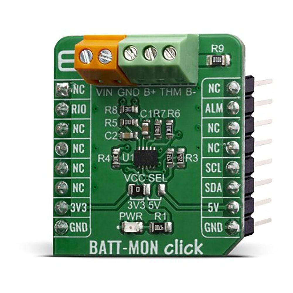
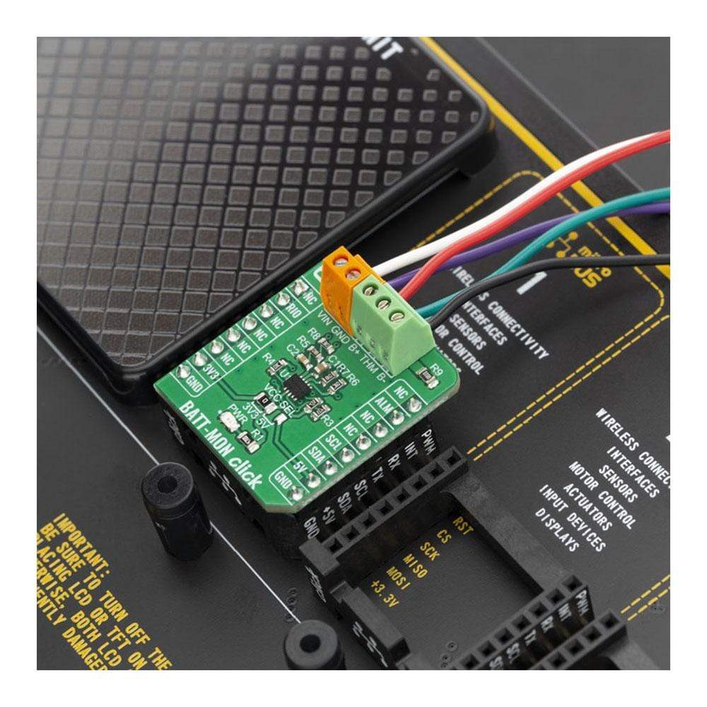
The BATT-MON Click Board™ is a very versatile, high accuracy, multiple-chemistry battery gauge for applications of single-cell batteries. It can be used for various applications, ranging from smartphones, notebooks/laptops, power tools, vacuums, to energy storage systems (ESS), while providing the output voltage at the same time. The interesting feature of this device is that it can provide additional current to the connected load if the current provided from the mikroBUS™ socket is not enough. This is possible by utilizing the connected battery and by employing intelligent power routing algorithms of the BATT-MON Click Board™.
Features like the OptimGaugeTM algorithm, 0.25% accuracy battery voltage monitoring, Coulomb counter, and voltage-mode gas gauge operations make the BATT-MON click specialized battery gauge IC, used to provide battery depletion data via the I2C interface, the BATT-MON Click Board™ can be used to charge and monitorLiPo/Li-Ion batteries for a wide range of applications that can benefit from reliable and efficient LiPo/Li-Ion battery charger, like the mobile phones, multimedia players, digital cameras, portable medical equipment, and many more.
How Does The BATT-MON Click Board™ Work?
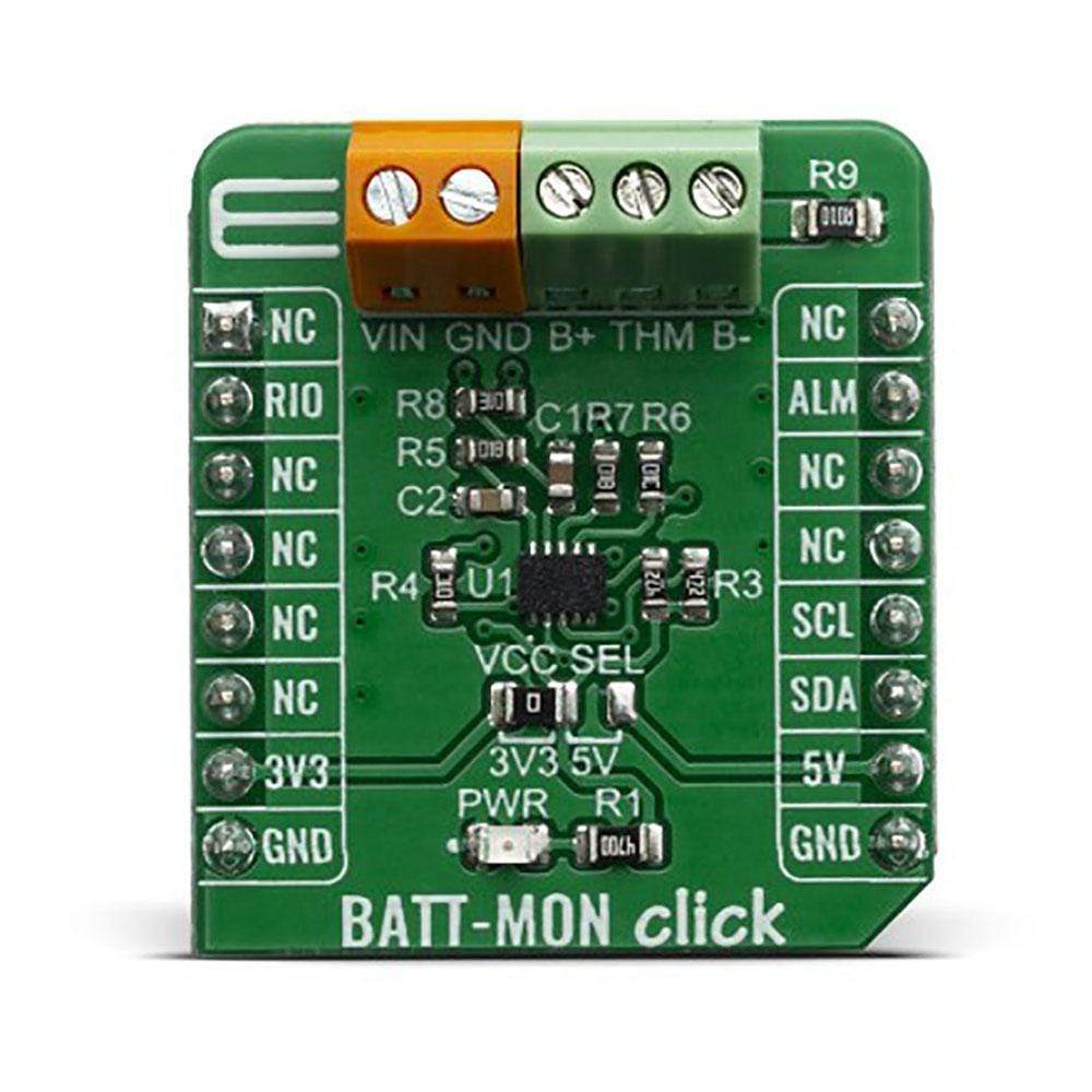
The core component of the BATT-MON Click Board™ is the STC3115, a high-precision battery gas gauge IC with alarm output for handheld applications, from STMicroelectronics. It includes all necessary components for the STC3115 to ensure the proper functionality of the Click board™ and maintain the monitoring precision.
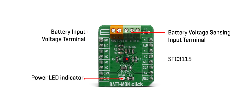
The monitoring functions include the measurement of battery voltage, current, and temperature. A Coulomb counter is available to track the SOC when the battery is charging or discharging at a high rate. A sigma-delta A/D converter is used to measure the voltage, current, and temperature. The STC3115 can operate in two different modes with different power consumption. Mode selection is made by the VMODE bit in register 0. For more information about registers and operating modes, refer to modes STC3115 datasheet.
Battery voltage is measured by using one conversion cycle of the A/D converter every 4 s. The conversion cycle takes 8192 clock cycles, which means that when the the internal 32768 Hz clock is used, the conversion cycle time is 250 ms. The voltage range is 0 to 4.5 V and resolution is 2.20 mV. Accuracy of the voltage measurement is ±0.5% over the temperature range. This allows accurate SOC information from the battery open-circuit voltage
For current sensing, the voltage drop across the sense resistor (R9) is measured with the internal 14-bit sigma-delta A/D converter. Using the 32768 Hz internal clock, the conversion cycle time is 500 ms for a 14-bit resolution. The LSB value is 5.88 μV. The A/D converter output is in two's complement format. When a conversion cycle is completed, the result is added to the Coulomb counter accumulator and the number of conversions is incremented in a 16-bit counter. The current register is updated only after the conversion closest to the voltage conversion (that is: once per 4-s measurement cycle). The result is stored in the REG_CURRENT register (see Table 12).
The voltage range which can be used to power up the BATT-MON Click Board™, allows for it to work with both 3.3V and 5V capable MCUs. It can be selected by soldering a small SMD jumper, labeled as VCC SEL to the correct position.
SPECIFICATIONS
Type | Battery charger |
Applications | The BATT-MON Click Board™ can be used for smartphones development, notebook / laptops, power tools, vacuums, to energy storage systems (ESS). |
On-board modules | STC3115, a high-precision battery gas gauge IC with alarm output for handheld applications, from STMicroelectronics |
Key Features | The BATT-MON Click Board™ features OptimGaugeTM algorithm, 0.25% accuracy battery voltage monitoring, Coulomb counter, and voltage-mode gas gauge operations |
Interface | GPIO,I2C |
Compatibility | mikroBUS |
Click board size | S (28.6 x 25.4 mm) |
Input Voltage | 3.3V or 5V |
Pinout Diagram
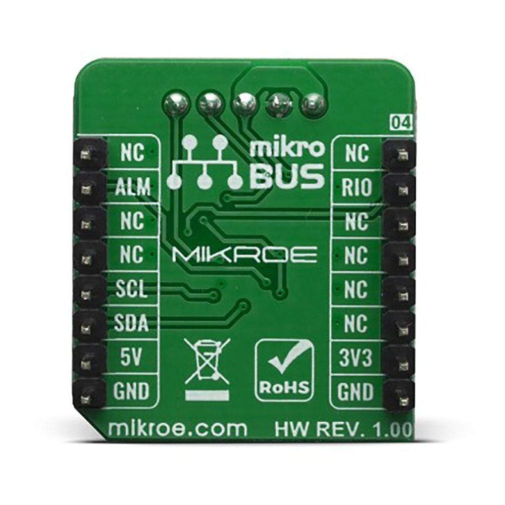
This table shows how the pinout of the BATT-MON Click Board™ corresponds to the pinout on the mikroBUS™ socket (the latter shown in the two middle columns).
Notes | Pin | Pin | Notes | ||||
---|---|---|---|---|---|---|---|
NC | 1 | AN | PWM | 16 | NC | ||
Reset sense input & reset control output | RIO | 2 | RST | INT | 15 | ALM | Alarm Out |
NC | 3 | CS | RX | 14 | NC | ||
NC | 4 | SCK | TX | 13 | NC | ||
NC | 5 | MISO | SCL | 12 | SCL | I2C Clock | |
NC | 6 | MOSI | SDA | 11 | SDA | I2C Data | |
Power Supply | 3.3V | 7 | 3.3V | 5V | 10 | 5V | Power Supply |
Ground | GND | 8 | GND | GND | 9 | GND | Ground |
ONBOARD SETTINGS AND INDICATORS
Label | Name | Default | Description |
---|---|---|---|
LD1 | PWR | - | Power LED Indicator |
JP1 | VCC SEL | Left | Enables switching regulator output, left position 3V3, right position 5V |
TB1 | TB1 | - | Battery voltage In/Out |
TB2 | TB2 | - | Battery connection terminal |
BATT-MON CLICK ELECTRICAL SPECIFICATIONS
Description | Min | Typ | Max | Unit |
---|---|---|---|---|
Operating current consumption | - | 45 | 60 | µA |
Current consumption in standby | - | - | 2 | µA |
Current sensing AD converter granularity | - | 5.88 | - | µA |
Battery Voltage measurement granularity | - | 2.20 | - | µA |
Software Support
We provide a library for the BATT-MON Click Board™ on our LibStock page, as well as a demo application (example), developed using MikroElektronika compilers. The demo can run on all the main MikroElektronika development boards.
Library Description
This library allows user to perform a battery monitoring. User can get battery voltage, battery current, temperature, SOC, OCV value from the device. This library offers a choice to set SOC and voltage alarm value and to check alarm interrupt status. For more details check documentation.
Key Functions
T_BATTMON_RETVAL battmon_readBytes( uint8_t regAddr, uint8_t *dataOut, uint8_t nBytes )
- This function reads the desired number of bytes starting from the selected register.T_BATTMON_RETVAL battmon_writeByte( uint8_t regAddr, uint8_t dataIn )
- This function writes one byte data to the selected register.float battmon_getData( uint8_t data_addr )
- This function allows user to get the desired data calculated to the properly unit.
Example Description
The application is composed of three sections :
- System Initialization - Initializes peripherals and pins.
- Application Initialization - Initializes I2C serial interface, reads the part ID and performs a device configuration and alarm setting.
- Application Task - (code snippet) - Checks the conversion counter value and when conversion was done reads data calculated to the properly unit and checks the alarm status. All results will be sent to the uart terminal. Note: Voltage and current conversion will be done after 4 seconds. Temperature conversion will be done after 16 seconds. After temperature reading the conversion counter will be cleared. Clearing the alarm while the corresponding low-voltage or low-SOC condition is still in progress does not generate another interrupt. This condition must disappear first and must be detected again before another interrupt (ALM pin driven low or alarm interrupt bits are set high) is generated for this alarm. Another alarm condition, if not yet triggered, can still generate an interrupt. Input voltage must be in the range from 2.7V to 4.5V. Maximal battery current is 5A.
void applicationTask() { conv_cnt = battmon_getData( _BATTMON_REG_COUNTER ); if (((conv_cnt % 4) == 0) && (conv_cnt > 0)) { data_read = battmon_getData( _BATTMON_REG_SOC ); FloatToStr( data_read, text ); floatCut(); mikrobus_logWrite( "** Gas Gauge Relative SOC : ", _LOG_TEXT ); mikrobus_logWrite( text, _LOG_TEXT ); mikrobus_logWrite( " %", _LOG_LINE ); data_read = battmon_getData( _BATTMON_REG_CURRENT ); FloatToStr( data_read, text ); floatCut(); mikrobus_logWrite( "** Battery Current : ", _LOG_TEXT ); mikrobus_logWrite( text, _LOG_TEXT ); mikrobus_logWrite( " mA", _LOG_LINE ); data_read = battmon_getData( _BATTMON_REG_VOLTAGE ); FloatToStr( data_read, text ); floatCut(); mikrobus_logWrite( "** Battery Voltage : ", _LOG_TEXT ); mikrobus_logWrite( text, _LOG_TEXT ); mikrobus_logWrite( " mV", _LOG_LINE ); if ((conv_cnt % 16) == 0) { data_read = battmon_getData( _BATTMON_REG_TEMPERATURE ); battmon_reset_conv_cnt(); FloatToStr( data_read, text ); floatCut(); mikrobus_logWrite( "** Temperature : ", _LOG_TEXT ); mikrobus_logWrite( text, _LOG_TEXT ); mikrobus_logWrite( cels_symbol, _LOG_LINE ); } reg_read = battmon_check_clear_alarm(); if ((reg_read & _BATTMON_ALM_SOC_DET_MASK) != _BATTMON_LOG_LOW) { mikrobus_logWrite( "** Low-SOC Condition!", _LOG_LINE ); alarmPlay(); } if ((reg_read & _BATTMON_ALM_VOLT_DET_MASK) != _BATTMON_LOG_LOW) { mikrobus_logWrite( "** Low-Voltage Condition!", _LOG_LINE ); alarmPlay(); } mikrobus_logWrite( "*********************************", _LOG_LINE ); Delay_ms( 1000 ); } else { Delay_ms( 200 ); } }
Additional Functions :
- floatCut - Allows to real values be rounded on two decimal places.
- alarmPlay - Makes sound on buzzer for alarm detection.
The full application code, and ready to use projects can be found on our LibStock page.
Other mikroE Libraries used in the example:
- Conversions
- I2C
- Sound
- UART
Additional Notes and Information
Depending on the development board you are using, you may need a USB UART click, USB UART 2 click or RS232 click to connect to your PC, for development systems with no UART to USB interface available on the board. The terminal available in all MikroElektronika compilers, or any other terminal application of your choice, can be used to read the message.
MIKROSDK
The BATT-MON Click Board™ is supported with mikroSDK - MikroElektronika Software Development Kit. To ensure proper operation of mikroSDK compliant Click board™ demo applications, mikroSDK should be downloaded from the LibStock and installed for the compiler you are using.
BATT-MON Click Board
Frequently Asked Questions
Have a Question?
Be the first to ask a question about this.