


Tag-Connect, LLC
Tag-Connect TC2030-IDC-10 6-Pin Legged Programming Cable
Tag-Connect TC2030-IDC-10 6-Pin Legged Programming Cable
SKU: TC2030-IDC-10
Couldn't load pickup availability
Key Features
Overview
The Tag-Connect TC2030-IDC-10 represents the extended-length variant of the industry-standard TC2030 programming interface, providing engineers with additional cable reach whilst maintaining the space-saving benefits of the Plug-of-Nails™ connector system. By eliminating the requirement for a mating header component on every PCB, this solution delivers significant cost savings and board space optimisation across production runs.
The legged design incorporates four precision-moulded plastic retention clips that engage securely with the PCB footprint, providing reliable hands-free operation essential for debugging workflows and extended programming sessions. The spring-loaded pogo pins are rated for over 100,000 connection cycles, ensuring long-term reliability in both development and production environments.
Also available in 6-inch length for applications requiring minimal signal path length, and no-legs variant for maximum footprint efficiency.
Downloads
Why Engineers Choose The Tag-Connect TC2030-IDC-10 6-Pin Legged Programming Cable
Extended Reach Capability
Hands-Free Debugging
Production Cost Savings
Professional 10-Inch Programming Cable with Secure PCB Connection
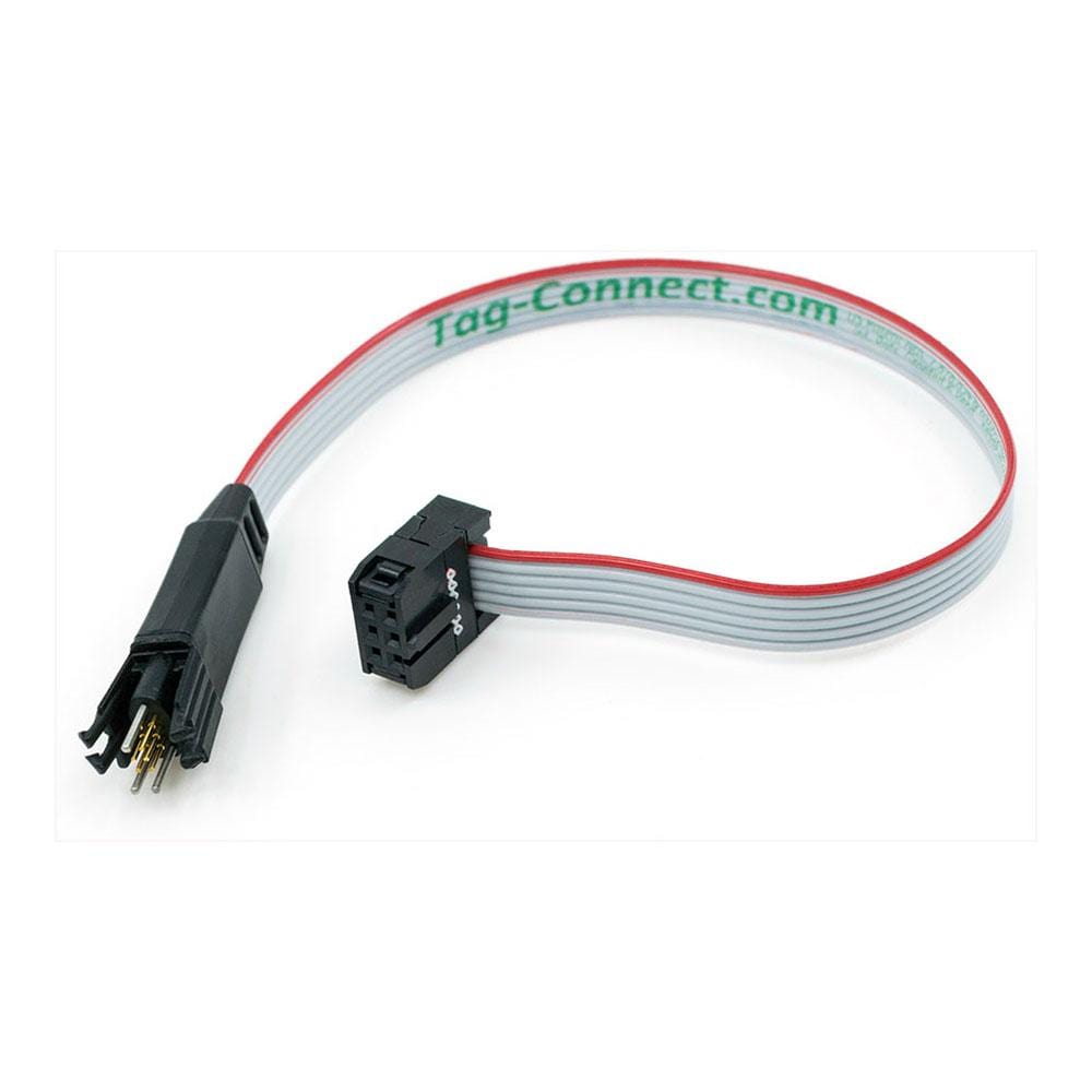
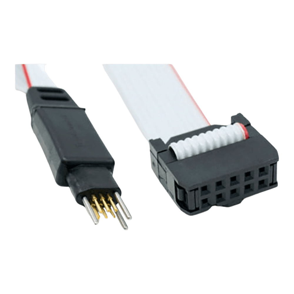
The TC2030-IDC-10 is Tag-Connect's 6-pin "Legged" Plug-of-Nails™ programming cable featuring a generous 10-inch (254mm) length and fitted with a 6-pin 0.1" pitch ribbon connector. This extended cable length provides enhanced flexibility for programming and debugging operations whilst maintaining the reliable connection quality expected from Tag-Connect products.
Legged Design for Secure Connection
The "Legged" or "With Legs" version features four plastic retention clips that snap directly into a specially designed footprint of holes and pads on your PCB. This self-securing mechanism provides hands-free operation during extended debugging sessions, eliminating the need for manual pressure to maintain connection integrity.
| Pin | Function | Description |
|---|---|---|
| 1 | VCC | Target power supply |
| 2 | SWDIO/TMS | Serial Wire Debug I/O / Test Mode Select |
| 3 | nRESET | Target reset (active low) |
| 4 | SWCLK/TCK | Serial Wire Debug Clock / Test Clock |
| 5 | GND | Ground reference |
| 6 | SWO/TDO | Serial Wire Output / Test Data Output |
PCB Footprint Requirements
The TC2030 footprint requires six contact pads arranged in a 2×3 configuration with 0.050" (1.27mm) spacing, plus four retention holes for the plastic legs and three alignment holes. The complete footprint occupies approximately 0.39" × 0.24" (9.9mm × 6.1mm) of PCB real estate.
Compatible Applications
- ARM Cortex-M microcontroller programming via SWD protocol
- Atmel AVR programming with ISP (In-System Programming)
- Renesas microcontroller programming (requires TC-Renesas adapter)
- General-purpose SPI, I2C, and serial signal access
- Custom test point access for production testing
The 10-inch cable length is particularly beneficial when working with larger development boards, test fixtures, or when the programmer must be positioned away from the target PCB. For high-speed signals, shorter cable lengths are generally preferred, making the standard 6-inch TC2030-IDC more suitable for critical timing applications.
| General Information | |
|---|---|
Part Number (SKU) |
TC2030-IDC-10
|
Manufacturer |
|
| Physical and Mechanical | |
Weight |
0.1 kg
|
| Other | |
EAN |
5055383690909
|
Frequently Asked Questions
Have a Question?
-
What is the expected lifespan of the pogo pin contacts?
The spring-loaded pogo pins are rated for over 100,000 mating cycles, providing exceptional durability for both development and high-volume production environments.
-
Can I retrofit existing boards designed for traditional headers?
No, the TC2030 requires a specific footprint pattern. However, you can design hybrid footprints that accept both Tag-Connect cables and traditional headers for flexibility.
-
What is the pin spacing and overall footprint dimensions?
Contact pads use 0.050" (1.27mm) spacing in a 2×3 arrangement. The complete legged footprint measures approximately 0.39" × 0.24" (9.9mm × 6.1mm) including retention holes.
-
How do I prevent solder paste from interfering with the connection?
Ensure your PCB design has zero-sized openings in the solder paste mask layer over the six contact pads. Most CAD packages default to adding paste mask openings which must be manually removed.
-
What debugger/programmer compatibility does this cable offer?
The 6-pin 0.1" IDC connector is compatible with most standard programmers including AVRISP, ST-LINK, J-LINK (with adapters), and many others. Check our <a href="https://thedebugstore.com/collections/tag-connect-adapters">adapter selection</a> for specific debugger compatibility.
-
Can this cable be used for production programming?
Absolutely. The secure legged connection makes it excellent for production programming where hands-free operation and connection reliability are essential for throughput.
-
Is the 10-inch length suitable for high-speed programming protocols?
For most applications yes, though shorter cables provide better signal integrity for very high-speed protocols. The 6-inch TC2030-IDC is recommended for critical timing applications.
-
What PCB footprint modifications are required for the legged version?
The legged footprint requires four additional retention holes (0.093" diameter) for the plastic clips plus three alignment holes, compared to the no-legs version which only needs the six contact pads and alignment holes.
-
Can I use this cable with ARM Cortex microcontrollers?
Yes, the TC2030-IDC-10 is fully compatible with ARM Cortex SWD programming when used with appropriate adapters such as the ARM20-CTX or direct connection to Cortex-10 debuggers.
-
What is the difference between TC2030-IDC-10 and TC2030-IDC-NL-10?
The TC2030-IDC-10 features four plastic legs that clip into the PCB footprint for secure hands-free connection, whilst the NL-10 version has no legs and requires manual pressure or a retaining clip for connection.