
SEGGER Microcontroller GmbH
SEGGER STDC 14 Adapter - 20-pin to 14-pin Debug Connector
SEGGER STDC 14 Adapter - 20-pin to 14-pin Debug Connector
SKU: 8.06.39
Couldn't load pickup availability

Key Features
Overview
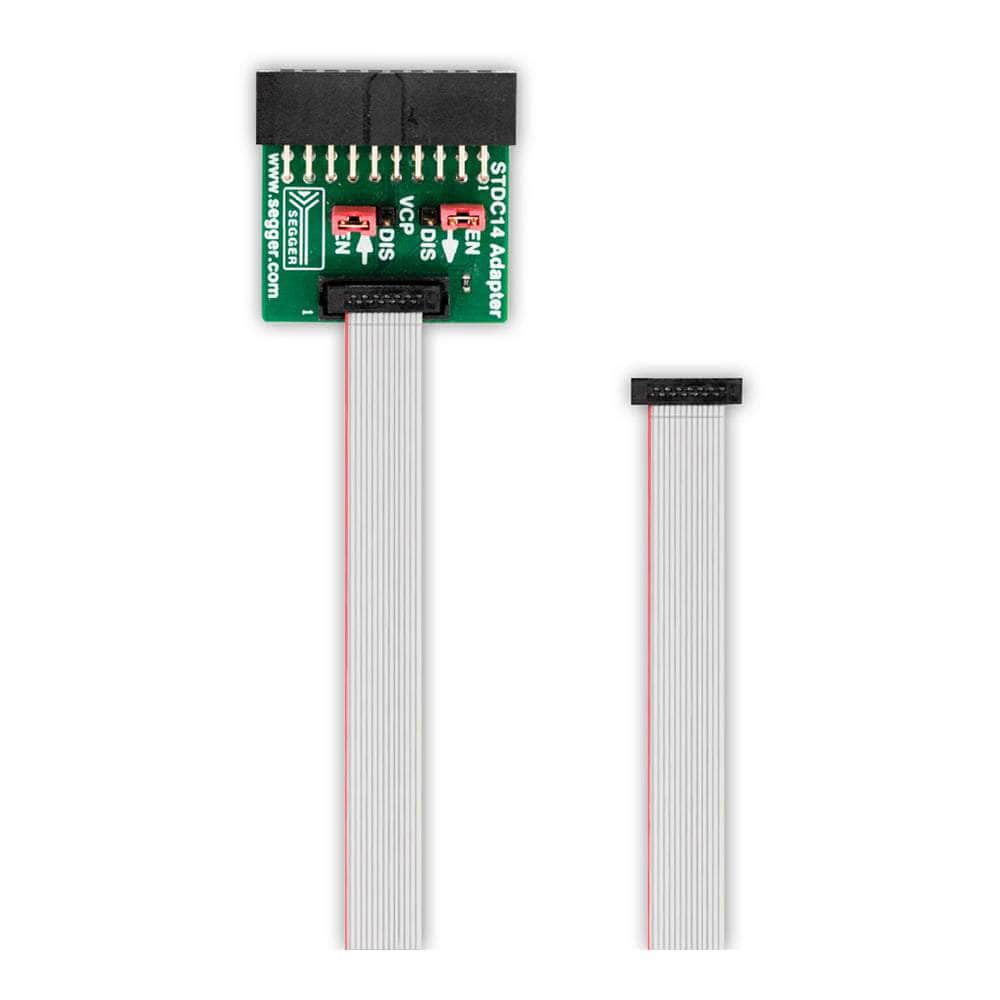
The SEGGER STDC 14 Adapter (8.06.39) enables seamless connection of J-Link and Flasher debug probes to targets featuring STMicroelectronics' 14-pin STDC connector. This passive adapter converts the standard 20-pin 0.1" J-Link connector to the compact 14-pin 0.05" STDC format, maintaining full compatibility with JTAG, SWD, and SWO debugging protocols.
Measuring just 25 x 25 x 11mm, the adapter provides direct electrical connectivity without active components, ensuring reliable signal integrity for Cortex-M and ARM7/9/11-based targets. The included 14-pin ribbon cable allows flexible routing to target systems whilst maintaining the sturdy construction required for repeated development use.
Compatible with the entire SEGGER ecosystem including J-Link Pro, Flasher ARM, and Tag-Connect STDC14 cables, this adapter expands debugging capabilities across STM32 evaluation boards and custom designs using the STDC14 standard.
Downloads
Why Engineers Choose The SEGGER STDC 14 Adapter - 20-pin to 14-pin Debug Connector
STM32 Development Compatibility
Cost-Effective Probe Extension
Professional Signal Integrity
Technical Overview
The SEGGER STDC 14 Adapter represents a critical interface solution for embedded systems developers working with STMicroelectronics' STDC14 connector standard. This passive adapter seamlessly bridges the gap between SEGGER's industry-standard 20-pin 0.1" J-Link connector and the compact 14-pin 0.05" STDC connector, maintaining full electrical compatibility across all supported debugging protocols.
Connector Specifications
| Pin | STDC14 Function | ARM10 Equivalent | Signal Type |
|---|---|---|---|
| 1-2 | Reserved | - | Not Connected |
| 3 | T_VCC | Pin 1 | Target Power |
| 4 | T_JTMS/T_SWDIO | Pin 2 | JTAG/SWD Data |
| 5 | GND | Pin 3 | Ground |
| 6 | T_JCLK/T_SWCLK | Pin 4 | Clock Signal |
| 7 | GND | Pin 5 | Ground |
| 8 | T_JTDO/T_SWO | Pin 6 | Trace Output |
| 9 | T_JRCLK | Pin 7 | Return Clock |
| 10 | T_JTDI | Pin 8 | JTAG Data In |
| 11 | GND_DETECT | Pin 9 | Ground Detect |
| 12 | T_NRST | Pin 10 | Reset Signal |
| 13 | T_VCP_RX | - | UART Receive |
| 14 | T_VCP_TX | - | UART Transmit |
Wiring Quick-Start
Connection setup requires no external power or configuration. Simply connect the adapter's 20-pin connector to your J-Link or Flasher probe, then connect the included 14-pin ribbon cable to your target system's STDC14 connector.
Compatible Hardware
The adapter supports the complete range of SEGGER debug probes including J-Link Pro PoE, J-Link Pro, J-Link ULTRA+, J-Link WiFi, J-Link PLUS series, and J-Link BASE series. All Flasher models are equally supported, providing maximum flexibility across development environments.
Target Applications
Primary applications include STM32 evaluation boards, custom STM32 designs, and any embedded system implementing the STDC14 connector standard. The adapter proves especially valuable in production environments where existing J-Link infrastructure must interface with newer STDC14-equipped targets.
| General Information | |
|---|---|
Product Type |
Adapter
|
Part Number (SKU) |
8.06.39
|
Manufacturer |
|
| Physical and Mechanical | |
Weight |
0.02 kg
|
| Other | |
EAN |
5055383602728
|
Frequently Asked Questions
Have a Question?
-
What's included in the STDC 14 Adapter package?
The package includes the STDC 14 Adapter PCB and a 14-pin ribbon cable with IDC connectors. No additional cables or accessories are required for basic operation with J-Link probes.
-
How does STDC14 compare to other debug connector options?
STDC14 offers more functionality than standard 10-pin ARM connectors by adding UART signals for Virtual COM port, whilst maintaining the same core debugging pins (3-12) as the ARM10 standard.
-
Does the adapter affect debugging performance or speed?
No, as a passive adapter it maintains the full debugging performance of the connected J-Link probe, including maximum download speeds up to 4.0 MB/s depending on the J-Link model used.
-
Can this adapter work with non-STMicroelectronics targets?
While designed for STMicroelectronics' STDC14 standard, the adapter will work with any target using the same 14-pin 0.05" connector pinout and electrical specifications.
-
What cable length is included with the adapter?
The adapter includes a 14-pin ribbon cable. The cable provides flexible routing between the adapter and target system.
-
Is any external power required for the adapter?
No, this is a passive adapter requiring no external power. It provides direct electrical connectivity between the 20-pin J-Link connector and 14-pin STDC connector without any active components.
-
What's the difference between the STDC14 and standard ARM 10-pin connectors?
STDC14 uses 14 pins at 0.05" pitch versus 10 pins at 0.05" pitch for standard ARM Cortex connectors. Pins 3-12 match the ARM10 pinout, with pins 1-2 reserved and pins 13-14 providing UART signals for Virtual COM port functionality.
-
Can I use Tag-Connect cables with this adapter?
Absolutely. The adapter is compatible with Tag-Connect STDC14 cables like the TC2030-CTX-STDC14, allowing connection to Tag-Connect footprints on target boards through the STDC14 interface.
-
Does the STDC 14 Adapter support SWO trace functionality?
Yes, the adapter fully supports Serial Wire Output (SWO) for trace debugging alongside standard JTAG and SWD protocols, maintaining all debugging capabilities of the connected J-Link probe.
-
What J-Link models are compatible with the STDC 14 Adapter?
The adapter works with all J-Link models including J-Link Pro PoE, Pro, ULTRA+, WiFi, PLUS Classic, PLUS Compact, BASE Classic, and BASE Compact. It's also compatible with all Flasher models.