


Tag-Connect, LLC
Tag-Connect TC2050-IDC-050-ALL Plug-of-Nails™ Cable
Tag-Connect TC2050-IDC-050-ALL Plug-of-Nails™ Cable
SKU: TC2050-IDC-050-ALL
Couldn't load pickup availability
Key Features
Overview
Overview
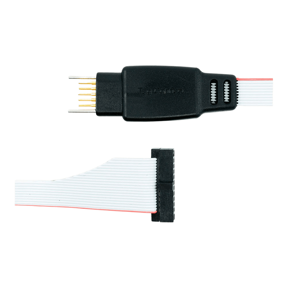
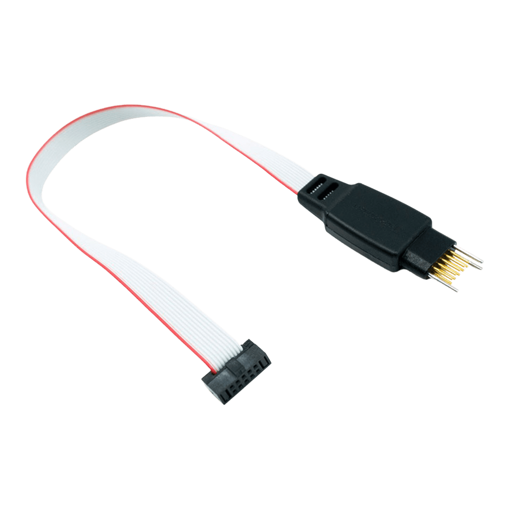
The Tag-Connect TC2050-IDC-050-ALL is a 10-pin “legged” Plug-of-Nails™ programming/debug cable that mates directly to a tiny TC2050 PCB footprint—no header required—and terminates in a 0.05″ (1.27 mm) 2×5 IDC plug. It connects 1:1 with all ten conductors present (including grounds and detect), making it suitable for ULINK2 and other tools using a Samtec FTSH-105-01 style micro-header.
Why Consider This Cable
For space-constrained boards, eliminating a fitted header saves BOM cost and height while retaining a secure, repeatable connection for SWD/JTAG during bring-up, test and production. The legged form factor self-retains for hands-free use.
Variants & Related Options
Also available in a No-Legs variant as TC2050-IDC-NL-050-ALL (use with a clip) and in a 20-pin micro-header version as TC2050-IDC-050-ALL-20. For ARM 20-pin (0.1″) pods, pair a TC2050 cable with the TC2050-ARM2010 adapter.
Typical Applications
ARM Cortex-M SWD/JTAG, FPGA/CPLD bring-up, in-line production programming, and boundary-scan on compact or sealed designs where a permanent connector is undesirable.
Downloads
Why Engineers Choose The Tag-Connect TC2050-IDC-050-ALL Plug-of-Nails™ Cable
Space & Cost Efficiency
Hands-Free Reliability
Tooling Compatibility
ARM Cortex Debug Interface Overview
The TC2050-IDC-050 provides seamless connectivity between ARM Cortex microcontrollers and debugging tools using the industry-standard 10-pin debug interface. This cable eliminates the need for permanent debug connectors on production boards whilst maintaining full debugging capabilities during development.Debug Protocol Compatibility
This cable supports both JTAG and SWD debugging protocols. JTAG (Joint Test Action Group) uses 4 signal pins for comprehensive debugging including boundary scan testing, whilst SWD (Serial Wire Debug) requires only 2 pins for efficient debugging of ARM Cortex processors.| Protocol | Pins Used | Key Signals | Advantages |
|---|---|---|---|
| JTAG | 4 | TCK, TMS, TDI, TDO | Full boundary scan, multi-device chain |
| SWD | 2 | SWDCLK, SWDIO | Fewer pins, ARM optimised, faster |
Wiring Quick-Start
The TC2050 footprint requires precise PCB layout for reliable connection. Contact pads must be 0.079" diameter with 0.100" spacing in a 2x5 configuration. Two 0.079" alignment holes are positioned to ensure correct cable orientation.TC2050 Pinout (Top View): 1 - VTG 2 - TMS/SWDIO 3 - GND 4 - TCK/SWCLK 5 - NC 6 - TDO/SWO 7 - GND 8 - TDI 9 - NC 10 - nRESET * Pins 5 and 9 not connected in standard version ULINK2 Debugger Integration
The cable's 0.050" pitch connector directly mates with ULINK2's Samtec FTSH-105-01 header. This configuration provides efficient debugging for ARM7, ARM9, and Cortex-M microcontrollers with full MDK-ARM integration.PCB Design Considerations
The TC2050 footprint requires careful PCB design attention. Keep-out areas around the connector ensure finger access for cable insertion. The footprint works on both 2-layer and multilayer boards with appropriate via placement.Alternative Configurations
Several variants exist for different debugging requirements: TC2050-IDC-050-ALL: All 10 pins connected for full JTAG compatibility TC2050-IDC-NL-050: No-legs version for production programming TC2050-IDC-050-LEMTA: Reversed connector for Atmel-ICE compatibility| General Information | |
|---|---|
Part Number (SKU) |
TC2050-IDC-050-ALL
|
Manufacturer |
|
| Other | |
EAN |
5055383642199
|
Frequently Asked Questions
Have a Question?
-
How does this compare with costlier test connectors?
Compared with fitted high-density board connectors and fixtures, Tag-Connect offers a compact, repeatable interface without permanent hardware on the PCB.
-
What footprint files are available?
See Tag-Connect’s footprint download packs and the TC2050-IDC datasheet for keep-out and drilling guidance.
-
Is there a 20-pin micro-header version?
Yes: the TC2050-IDC-050-ALL-20">TC2050-IDC-050-ALL-020 mates to 0.05″ 2×10 micro-headers while only wiring pins 1-10 in the ribbon.
-
Can I use it for SWD and full JTAG?
Yes. The 10-pin mapping supports common SWD and JTAG signals. Always verify your tool’s pinout.
-
How is this different from leaving a 10-pin header on the board?
You save BOM cost and height; the TC2050 footprint has effectively zero height yet remains robust for repeated use during development and production.
-
What is “LEMTA”?
A variant with ribbon reversal for Atmel-ICE compatibility. If you need Atmel-ICE, choose the LEMTA option.
-
What does “ALL” signify?
All ten conductors are present; grounds and detect lines are carried through. This simplifies compatibility versus selective-pin versions.
-
Which debuggers does this cable suit?
Any pod with a 0.05″ (MIPI-10) micro-header—e.g., ULINK2 and similar. For ARM 20-pin (0.1″) pods, use a TC2050 cable with the TC2050-ARM2010 adapter.
-
What is the difference between the legged and the no-legs versions?
Legged versions self-retain on the PCB. No-legs versions need a retainer such as the TC2050-CLIP for hands-free operation.
-
What does “Plug-of-Nails™” mean?
It refers to the pogo-pin connector that mates with a simple PCB footprint (pads + guide holes), eliminating a soldered header while providing reliable contact.