Key Features
Overview
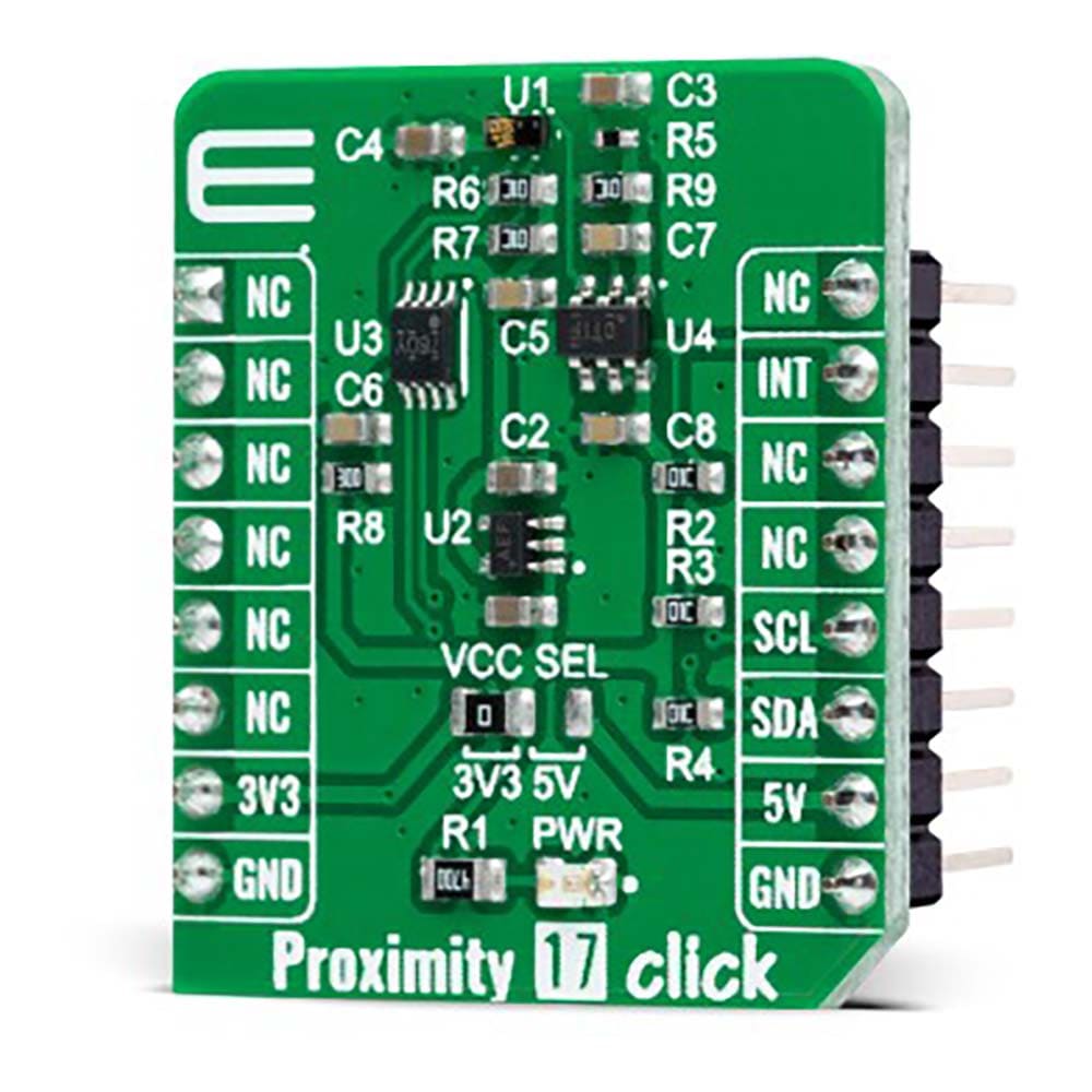
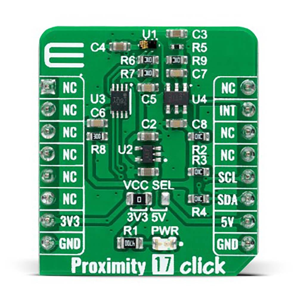
The Proximity 17 Click Board™ is a compact add-on board that contains a close-range proximity sensing solution. This board features the TMD2635, a miniature proximity sensor module from AMS AG. The TMD2635 features advanced proximity measurement in a tiny and thin optical land grid array module that incorporates a 940nm infrared vertical-cavity surface-emitting laser (IR VCSEL) factory calibrated for IR proximity response. It also offers advanced crosstalk noise cancellation through a wide range of offset adjustments through a digital fast-mode I2C interface to compensate for unwanted IR energy reflection at the sensor. This Click board™ is suitable for consumer and industrial applications.
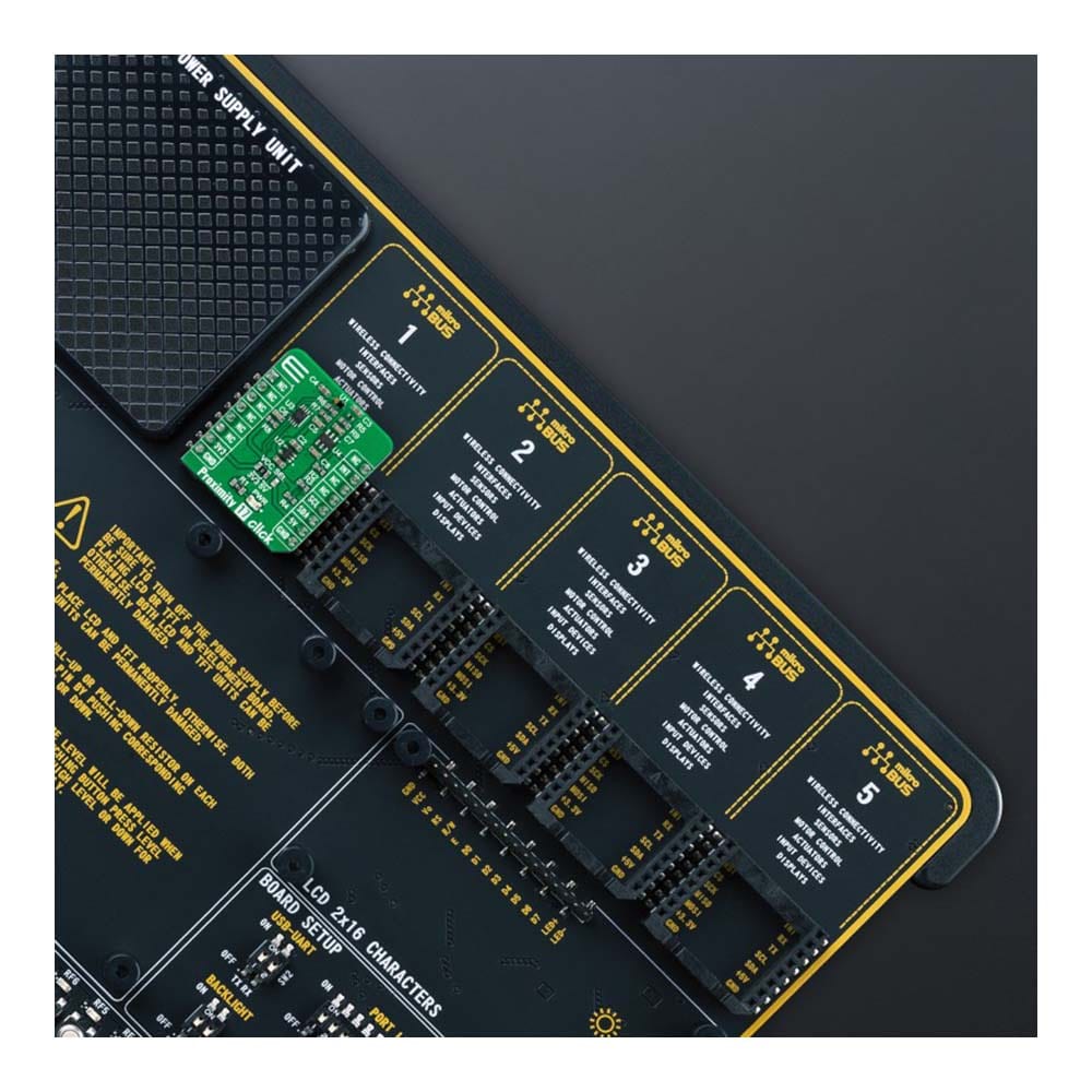
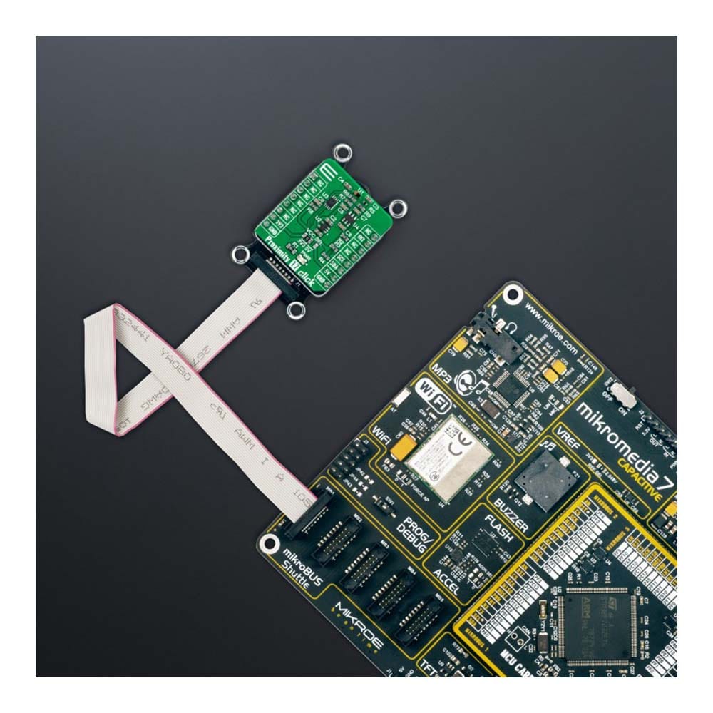
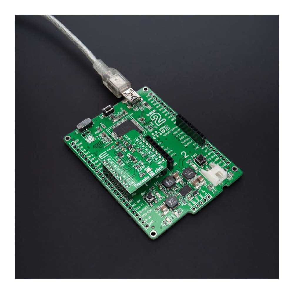
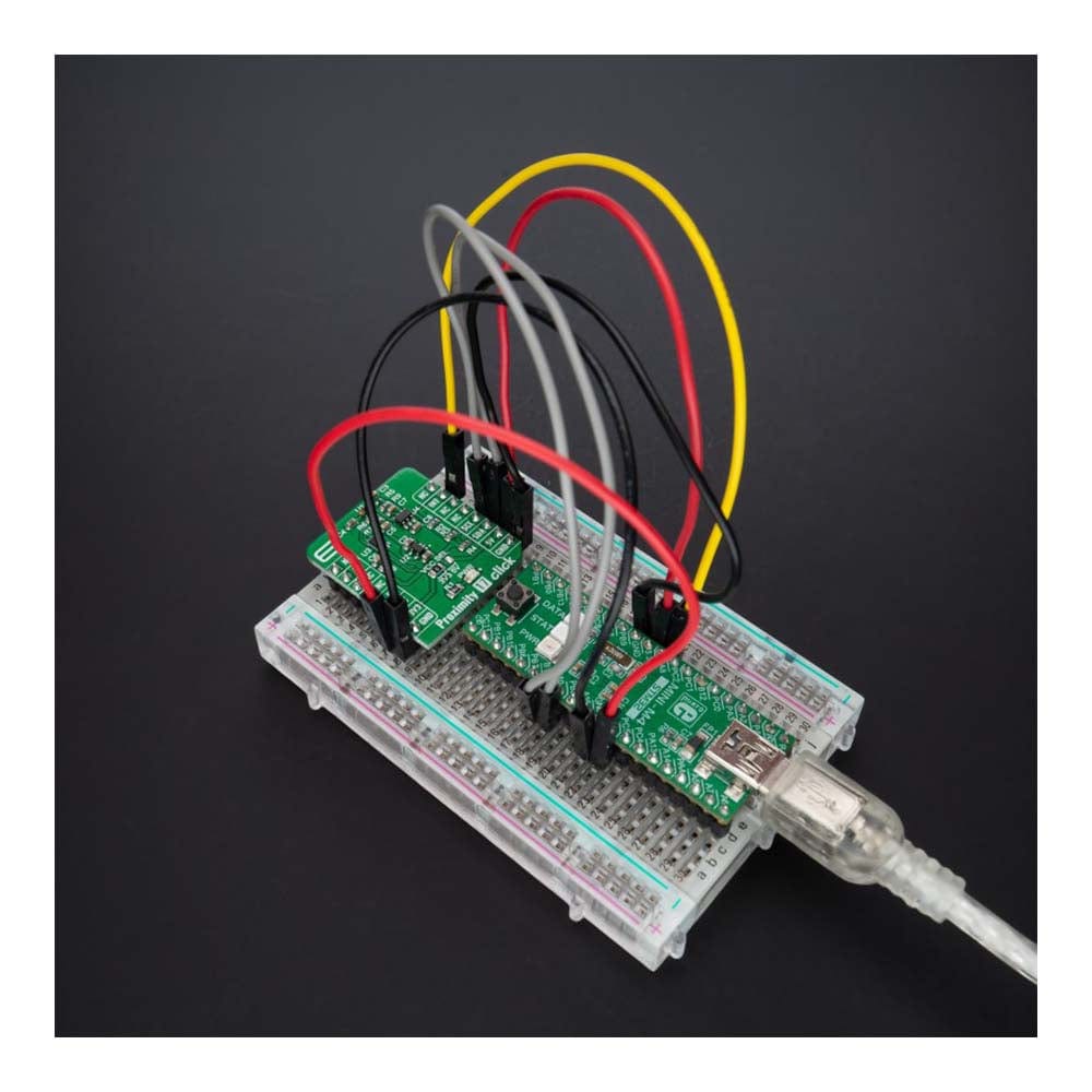
The Proximity 17 Click Board™ is supported by a mikroSDK compliant library, which includes functions that simplify software development. This Click board™ comes as a fully tested product, ready to be used on a system equipped with the mikroBUS™ socket.
Downloads
How Does The Proximity 17 Click Board™ Work?
The Proximity 17 Click Board™ is based on the TMD2635, a miniature close-range proximity sensor module from AMS AG. The TMD2635 implements a 940nm infrared VCSEL (Vertical Cavity Surface Emitting Laser) factory calibrated for IR proximity response, alongside a digital I2C serial interface. The proximity detection feature provides object detection (e.g., close proximity) by photodiode detection of reflected IR energy sourced by the integrated VCSEL emitter. The proximity engine also features a wide range offset adjustment to compensate for unwanted IR energy reflection at the sensor. The results are further improved by automatic ambient light subtraction.
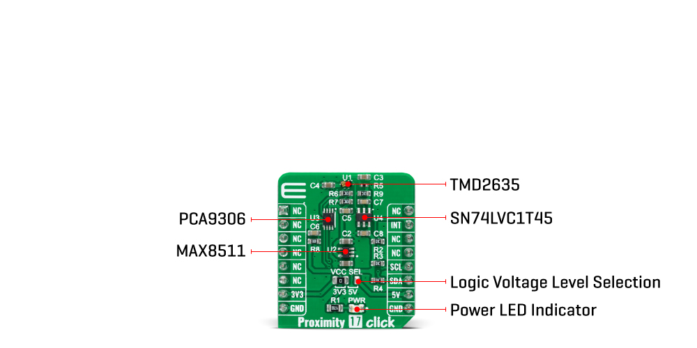
The TMD2635 does not require a specific Power-Up sequence but requires a supply voltage of 1.8V to work correctly. Therefore, a small regulating LDO is used, the MAX8511, providing a 1.8V out of both 5V and 3.3V mikroBUS™ power rails. Also, it can be shut down through software with a low standby current, allowing the power rails to remain powered at all times.
The Proximity 17 Click Board™ communicates with MCU using the standard I2C 2-Wire interface with a maximum clock frequency of 400kHz, fully adjustable through software registers with a 14-bit proximity result stored in a PDATA register. Since the sensor for operation requires a power supply of 1.8V, this Click board™ also features the PCA9306 and SN74LVC1T45 voltage-level translators. The I2C interface bus lines are routed to the voltage-level translators allowing this Click board™ to work with both 3.3V and 5V MCUs properly. Also, it uses an interrupt pin, the INT pin of the mikroBUS™ socket, used for when an interrupt occurs to alert the system when proximity result crosses upper or lower threshold settings.
The Proximity 17 Click Board™ can operate with both 3.3V and 5V logic voltage levels selected via the VCC SEL jumper. This way, it is allowed for both 3.3V and 5V capable MCUs to use the communication lines properly. However, the Click board™ comes equipped with a library that contains easy-to-use functions and an example code that can be used, as a reference, for further development.
SPECIFICATIONS
| Type | Proximity |
| Applications | The Proximity 17 Click Board™ can be used for consumer and industrial applications |
| On-board modules | TMD2635 - miniature close-range proximity sensor module from ams AG |
| Key Features | Low power consumption, enables superior proximity detection, integrated factory calibrated 940nm IR VCSEL, crosstalk and ambient light cancellation, dual photodiode architecture, shutdown and interrupt feature, and more |
| Interface | I2C |
| Compatibility | mikroBUS |
| Click board size | S (28.6 x 25.4 mm) |
| Input Voltage | 3.3V or 5V |
PINOUT DIAGRAM
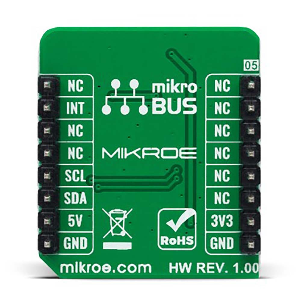
This table shows how the pinout of the Proximity 17 Click Board™ corresponds to the pinout on the mikroBUS™ socket (the latter shown in the two middle columns).
| Notes | Pin |  |
Pin | Notes | |||
|---|---|---|---|---|---|---|---|
| NC | 1 | AN | PWM | 16 | NC | ||
| NC | 2 | RST | INT | 15 | INT | Interrupt | |
| NC | 3 | CS | RX | 14 | NC | ||
| NC | 4 | SCK | TX | 13 | NC | ||
| NC | 5 | MISO | SCL | 12 | SCL | I2C Clock | |
| NC | 6 | MOSI | SDA | 11 | SDA | I2C Data | |
| Power Supply | 3.3V | 7 | 3.3V | 5V | 10 | 5V | Power Supply |
| Ground | GND | 8 | GND | GND | 9 | GND | Ground |
ONBOARD SETTINGS AND INDICATORS
| Label | Name | Default | Description |
|---|---|---|---|
| LD1 | PWR | - | Power LED Indicator |
| JP1 | VCC SEL | Left | Logic Level Voltage Selection 3V3/5V: Left position 3V3, Right position 5V |
PROXIMITY 17 CLICK ELECTRICAL SPECIFICATIONS
| Description | Min | Typ | Max | Unit |
|---|---|---|---|---|
| Proximity 17 Click | 3.3 | - | 5 | V |
| Wavelenght | - | 940 | - | nm |
| Operating Temperature Range | -30 | +25 | +85 | °C |
| General Information | |
|---|---|
Part Number (SKU) |
MIKROE-5084
|
Manufacturer |
|
| Physical and Mechanical | |
Weight |
0.02 kg
|
| Other | |
Country of Origin |
|
HS Code Customs Tariff code
|
|
EAN |
8606027389023
|
Warranty |
|
Frequently Asked Questions
Have a Question?
Be the first to ask a question about this.

