

Overview
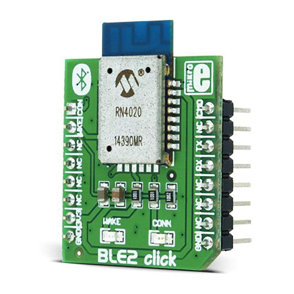
The BLE 2 Click Board™ is an excellent choice if you want simple, temporary connectivity with your smart devices over Bluetooth 4.1.
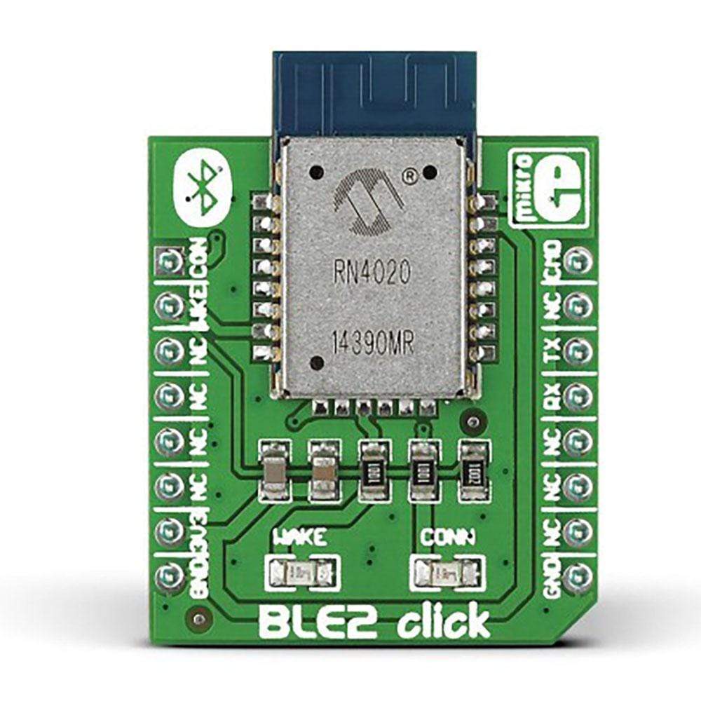
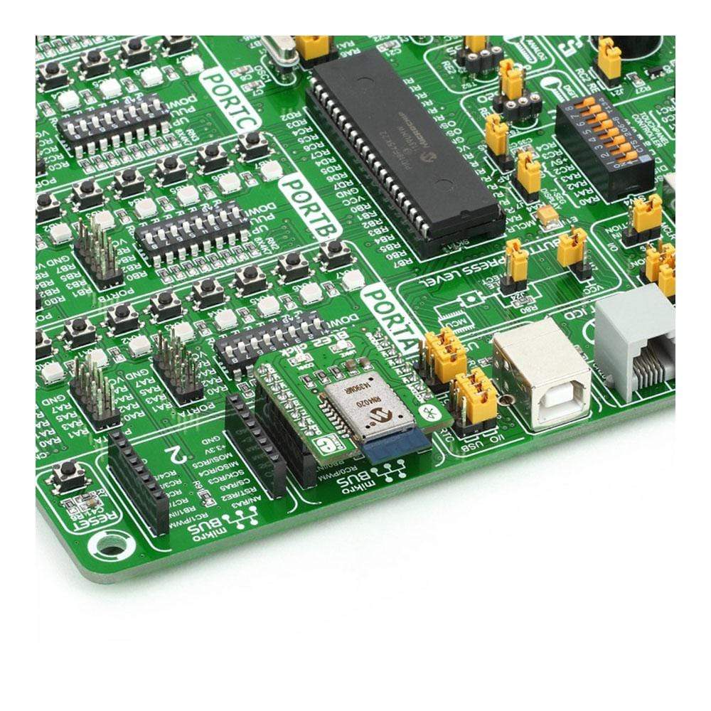
The BLE 2 Click Board™ features the RN4020 module from Microchip, which integrates RF, a baseband controller, and a command API processor, making it a complete Bluetooth Low Energy solution. The Click Board™ communicates with the target board MCU through MikroBUSRX, TX and AN (CMD), PWM (con.), and RST (wake) lines. The board is designed to use a 3.3V power supply only.
Downloads
The BLE2 Click Board™ is an excellent choice if you want simple, temporary connectivity with your smart devices over Bluetooth 4.1.
The BLE2 Click Board™ features the RN4020 module from Microchip, which integrates RF, a baseband controller, and a command API processor, making it a complete Bluetooth Low Energy solution. The click communicates with the target board MCU through mikroBUS™ RX, TX and AN (CMD), PWM (con.), and RST (wake) lines. The board is designed to use a 3.3V power supply only.
Microchip Low-energy Data Profile
The RN4020 has Microchip's Low-energy Data Profile (MLDP) which enables an asynchronous serial data connection between two RN4020 devices (which could be two BLE2 Click Board™s). The module can be remotely controlled or updated over the air by another module over a secure connection or can be controlled or updated through its UART interface.
PCB trace Antenna
The RN4020 module aboard BLE2 click incorporates a PCB antenna with a range of at least 30m.
Bluetooth 4.1
Bluetooth 4.1 is intended for IoT, it has low power consumption and lets any device be a peripheral and a hub at the same time.
Specifications
| Type | BT/BLE |
| Applications | Bluetooth Low Energy is becoming a pervasive standard for IoT applications in any number of domains (home automation, fitness, health and so on). Because of MLDP support, BLE2 click works great in pairs |
| On-board modules | Microchip RN4020 |
| Key Features | N4020 Bluetooth 4.1 module. PCB antenna. Integrated TCP/IP stack |
| Interface | GPIO, UART |
| Compatibility | mikroBUS |
| Click board size | S (28.6 x 25.4 mm) |
| Input Voltage | 3.3V |
Pinout diagram
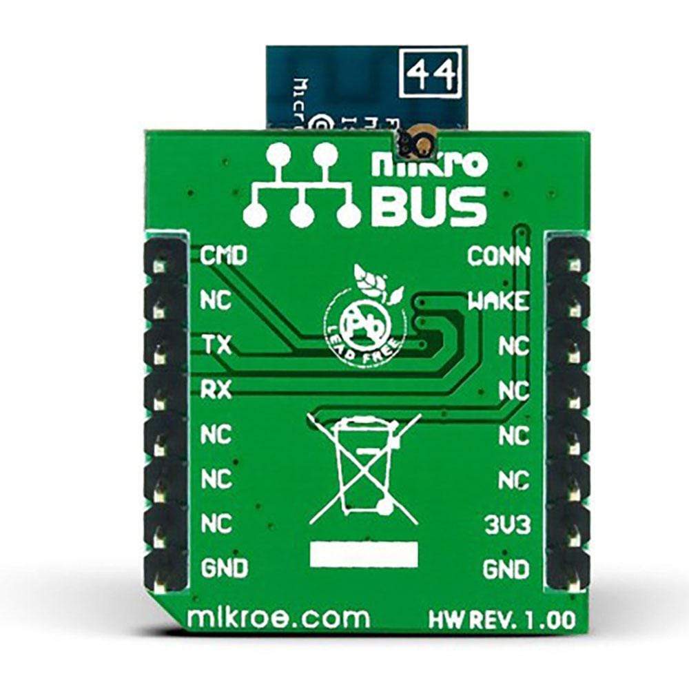
This table shows how the pinout on the BLE2 Click Board™ corresponds to the pinout on the mikroBUS™ socket (the latter shown in the two middle columns).
| Notes | Pin |  |
Pin | Notes | |||
|---|---|---|---|---|---|---|---|
| Indicates connection state | CONN | 1 | AN | PWM | 16 | CMD/MLDP | Command or MLDP mode |
| Deep Sleep Wake | SWAKE | 2 | RST | INT | 15 | NC | |
| NC | 3 | CS | TX | 14 | BT_UART_TX | UART Transmit | |
| NC | 4 | SCK | RX | 13 | BT_UART_RX | UART Receive | |
| NC | 5 | MISO | SCL | 12 | NC | ||
| NC | 6 | MOSI | SDA | 11 | NC | ||
| Power supply | +3.3V | 7 | 3.3V | 5V | 10 | NC | |
| Ground | GND | 8 | GND | GND | 9 | GND | Ground |
| General Information | |
|---|---|
Part Number (SKU) |
MIKROE-1715
|
Manufacturer |
|
| Physical and Mechanical | |
Weight |
0.03 kg
|
| Other | |
Country of Origin |
|
HS Code Customs Tariff code
|
|
EAN |
8606015077574
|
Warranty |
|
Frequently Asked Questions
Have a Question?
Be the first to ask a question about this.


