Key Features
Overview
Introducing the DC Motor 25 Click Board™ - The Ultimate Brushed DC Motor Driver!
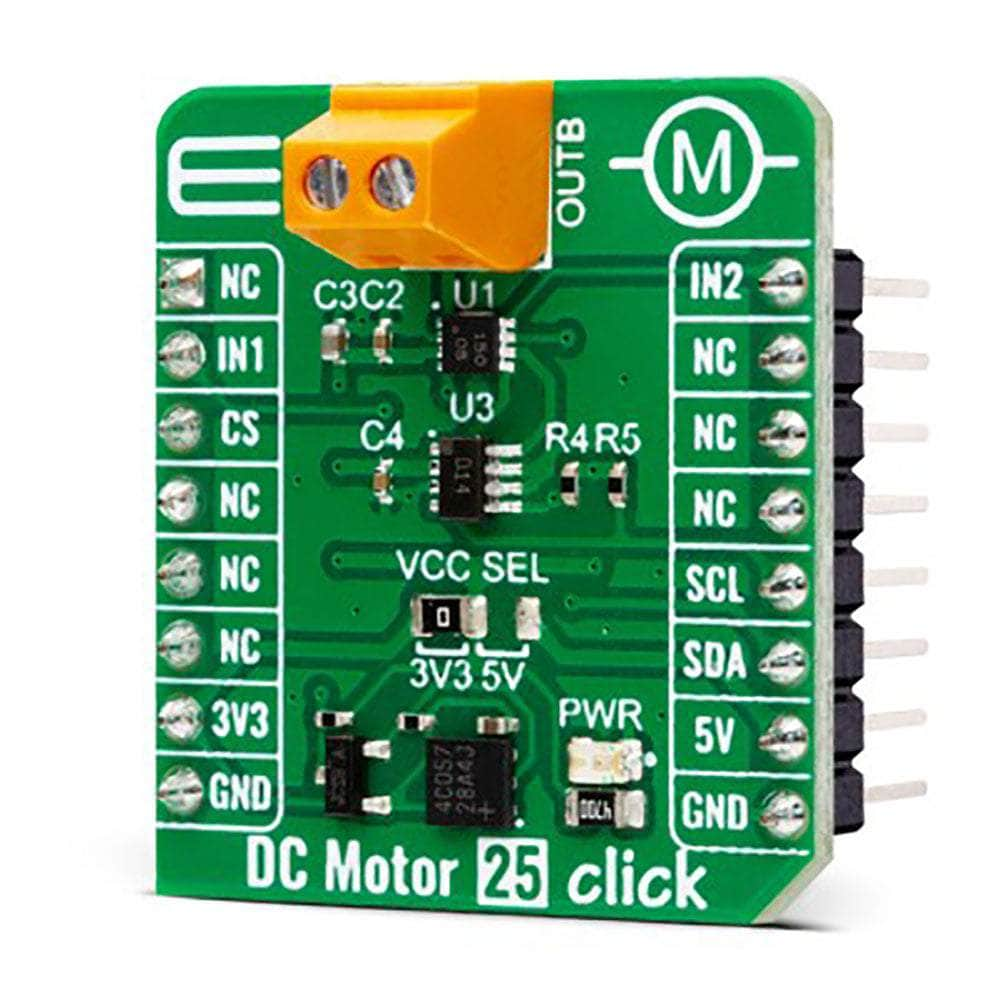
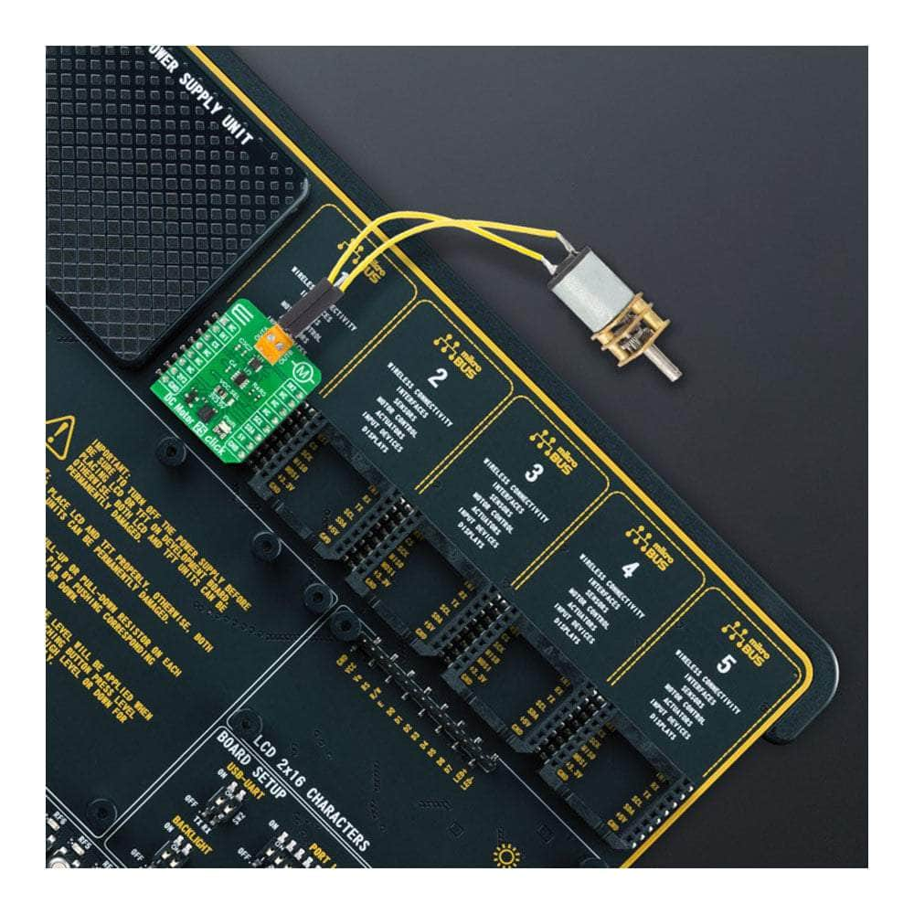
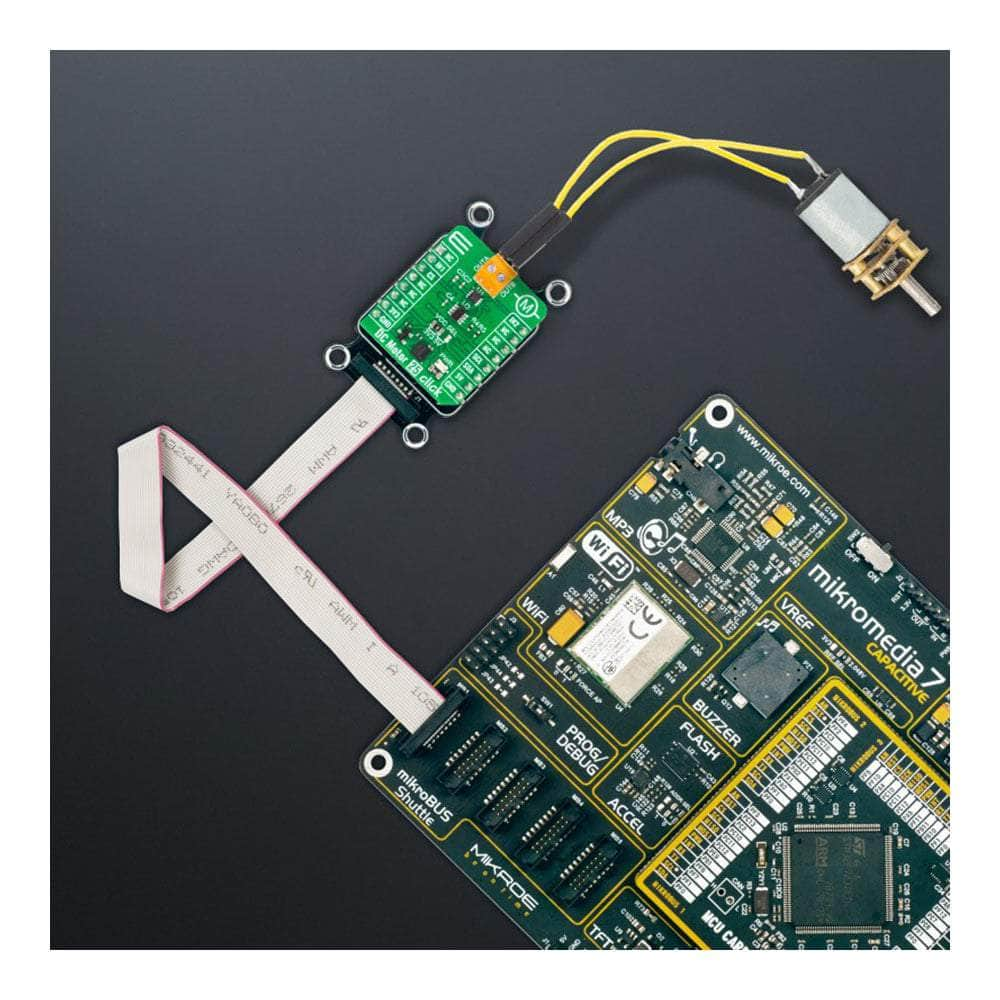
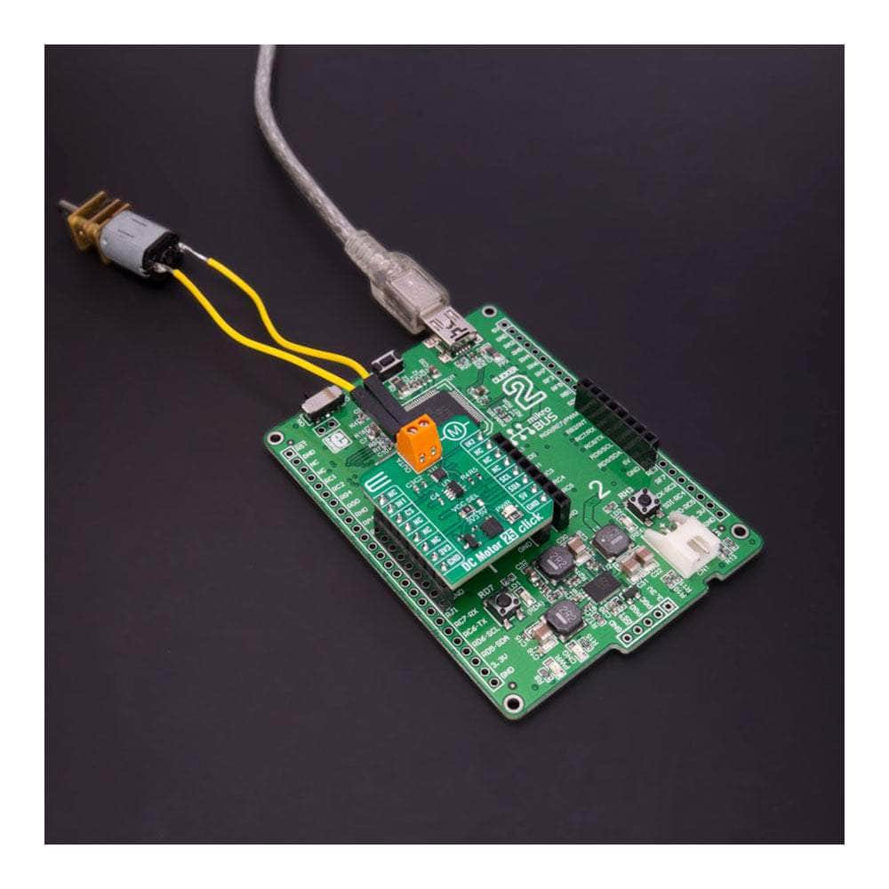
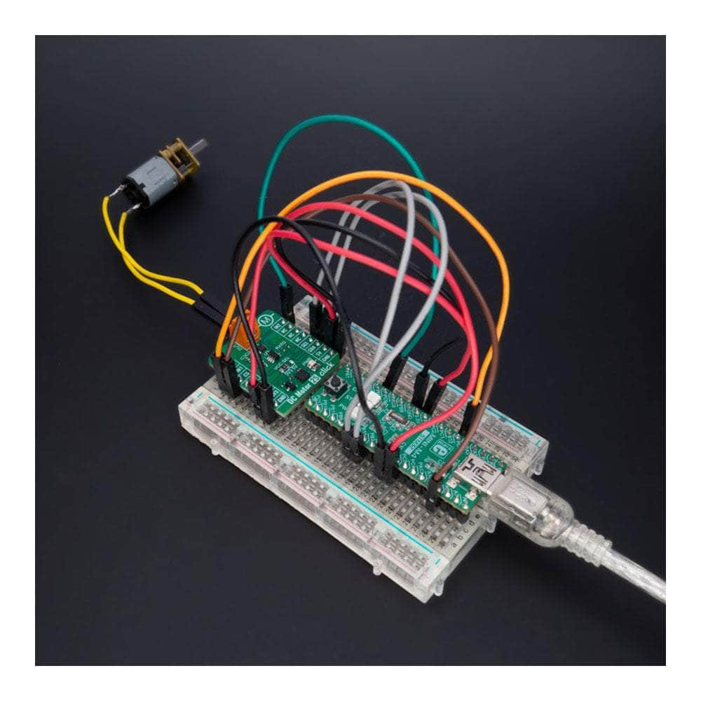
Unlock the full potential of your brushed DC motors with the all-new DC Motor 25 Click Board™! This compact add-on board is designed to deliver outstanding performance and versatility, thanks to the cutting-edge A3908 low-voltage bidirectional DC motor driver from Allegro Microsystems.
Experience Unparalleled Power and Efficiency
With an operating voltage range fully compatible with mikroBUS™ power rails and able to handle output currents of up to 500mA, the DC Motor 25 Click Board™ is perfect for a wide range of applications. Its unique output full-bridge incorporates source-side linear operation, ensuring a constant voltage across the motor coil for maximum efficiency.
Enjoy Ultimate Control and Flexibility
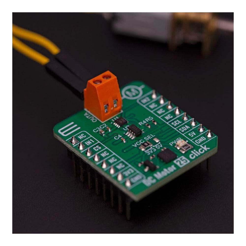
Logic input pins are at your disposal for precise control over the motor's direction of rotation, brake, and standby modes. This means you can easily fine-tune your device's performance to fit your specific needs, whether it's robotic actuators, pumps, battery-powered toys and games, low-noise instrumentation systems, or any other application that requires a reliable DC motor driver.
Stay Protected with Complete Protection Capabilities
The DC Motor 25 Click Board™ comes equipped with comprehensive protection features, ensuring robust and reliable operation in even the most demanding environments. Keep your devices running smoothly and safely, no matter the challenge.
Effortless Software Development with mikroSDK
Thanks to its mikroSDK-compliant library, the DC Motor 25 Click Board™ streamlines software development by providing you with various helpful functions. This means you can spend less time coding and more time enjoying your newly enhanced devices!
Plug and Play for a Seamless Experience
Designed for immediate use on a system equipped with a mikroBUS™ socket, the DC Motor 25 Click Board™ comes as a fully tested product. Get ready to experience the future of brushed DC motor drivers today!
Downloads
How Does The DC Motor 25 Click Board™ Work?
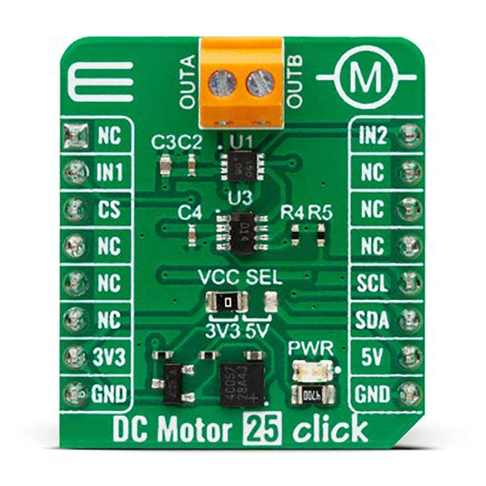
The DC Motor 25 Click Board™ is based on the A3908, a fully integrated low-voltage motor driver for DC motors from Allegro Microsystems. This Click board™ provides all the input and output capabilities necessary to drive DC motors (OUT terminal), alongside monitor diagnostic functions. The A3908 is rated for an operating voltage range compatible with both mikroBUS™ power rails and output currents up to 500mA, programmable via an external I2C-configurable digital potentiometer, the AD5171 from Analog Devices. The A3908 also has complete protection capabilities like thermal shutdown, undervoltage lockout, and crossover current (shoot-through) protection, allowing robust and reliable operation.
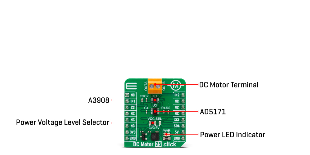
Logic pins labelled IN1 and IN2, routed on the default positions of RST and PWM pins of the mikroBUS socket, are provided to control the motor direction of rotation, brake, and standby modes. When both pins are in a high logic state, the A3908 goes into high-side brake mode, which turns on both source drivers. There is no protection during braking, so care must be taken to ensure that the peak current does not exceed the absolute maximum current.
Th DC Motor 25 Click Board™ can operate with either 3.3V or 5V logic voltage levels selected via the VCC SEL jumper. This way, both 3.3V and 5V capable MCUs can use the communication lines properly. However, the Click board™ comes equipped with a library containing easy-to-use functions and an example code that can be used, as a reference, for further development.
SPECIFICATIONS
| Type | Brushed |
| Applications | It can be used for robotic actuators and pumps, battery-powered toys and games, low-noise instrumentation systems, and more |
| On-board modules | A3908 - bidirectional DC motor driver from Allegro Microsystems |
| Key Features | Adjustable output current up to 500mA, driver control via logic pins, additional operational modes, internal protection, wide operating voltage range, low power consumption, and more |
| Interface | GPIO, I2C |
| Compatibility | mikroBUS |
| Click board size | S (28.6 x 25.4 mm) |
| Input Voltage | 3.3V or 5V |
PINOUT DIAGRAM
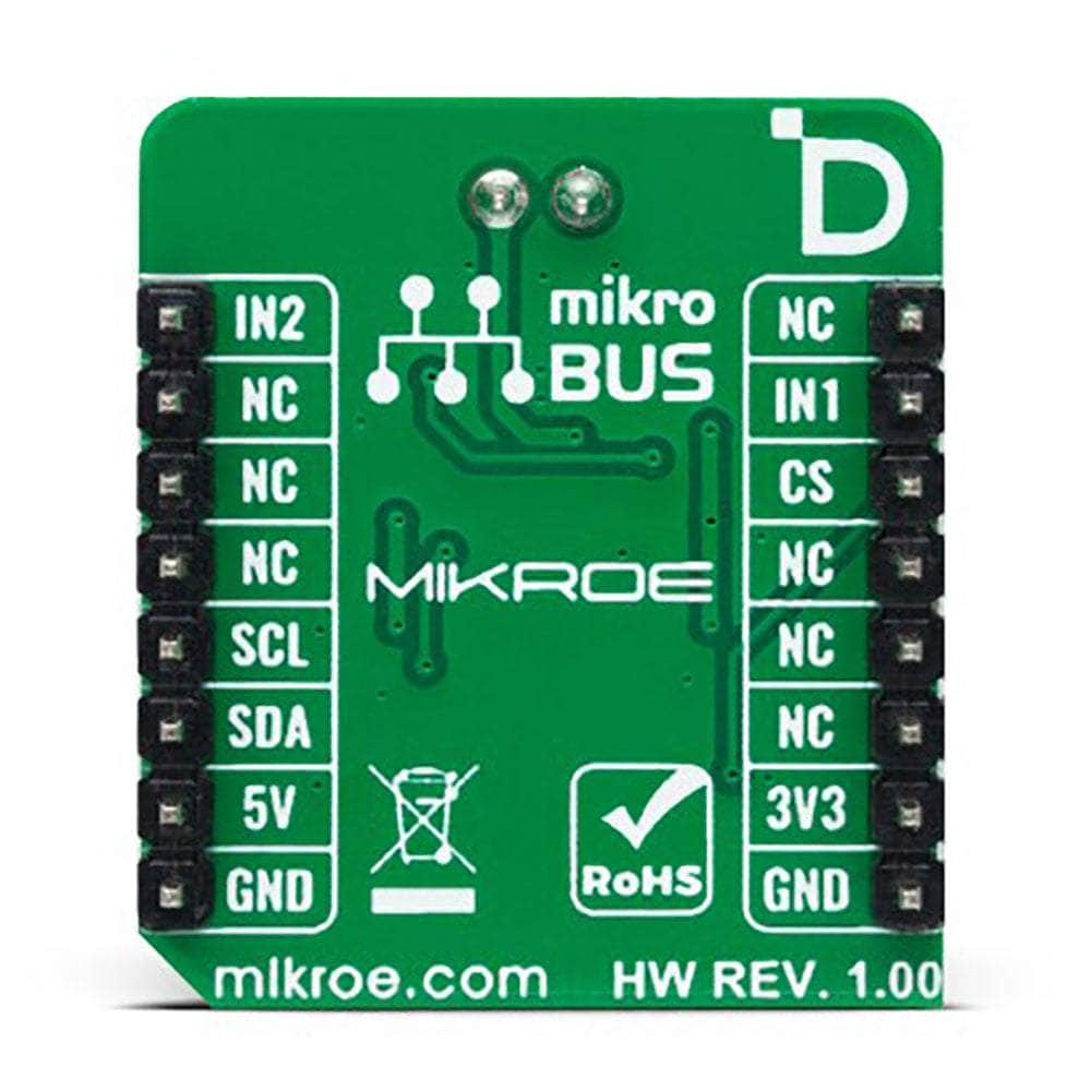
This table shows how the DC Motor 25 Click Board™ pinout corresponds to the pinout on the mikroBUS™ socket (the latter shown in the two middle columns).
| Notes | Pin |  |
Pin | Notes | |||
|---|---|---|---|---|---|---|---|
| NC | 1 | AN | PWM | 16 | IN2 | Driver Control 2 | |
| Driver Control 1 | IN1 | 2 | RST | INT | 15 | NC | |
| NC | 3 | CS | RX | 14 | NC | ||
| NC | 4 | SCK | TX | 13 | NC | ||
| NC | 5 | MISO | SCL | 12 | SCL | I2C Clock | |
| NC | 6 | MOSI | SDA | 11 | SDA | I2C Data | |
| Power Supply | 3.3V | 7 | 3.3V | 5V | 10 | 5V | Power Supply |
| Ground | GND | 8 | GND | GND | 9 | GND | Ground |
ONBOARD SETTINGS AND INDICATORS
| Label | Name | Default | Description |
|---|---|---|---|
| LD1 | PWR | - | Power LED Indicator |
| JP1 | VCC SEL | Left | Power Voltage Level Selection 3V3/5V: Left position 3V3, Right position 5V |
DC MOTOR 25 CLICK ELECTRICAL SPECIFICATIONS
| Description | Min | Typ | Max | Unit |
|---|---|---|---|---|
| Supply Voltage | 3.3 | - | 5 | V |
| Output Current | - | - | 500 | mA |
| General Information | |
|---|---|
Part Number (SKU) |
MIKROE-5523
|
Manufacturer |
|
| Physical and Mechanical | |
Weight |
0.02 kg
|
| Other | |
Country of Origin |
|
HS Code Customs Tariff code
|
|
EAN |
8606027384974
|
Warranty |
|
Frequently Asked Questions
Have a Question?
-
Is the DC Motor 25 Click Board™ a tested product?
Yes, the DC Motor 25 Click Board™ comes as a fully tested product, ready for use on a system equipped with the mikroBUS™ socket.
-
What is the mikroBUS™ socket?
The mikroBUS™ socket is a standardized interface that allows you to connect various Click boards™ to a development system. The DC Motor 25 Click Board™ is designed to be used with a system equipped with a mikroBUS™ socket.
-
How can I develop software for the DC Motor 25 Click Board™?
The DC Motor 25 Click Board™ is supported by a mikroSDK-compliant library, which includes functions that simplify software development. You can use these functions to create your software for controlling DC motors easily.
-
What kind of protection capabilities does the DC Motor 25 Click Board™ offer?
The board has complete protection capabilities, including overcurrent protection and thermal protection, ensuring robust and reliable operation.
-
How is the motor direction of rotation controlled?
The DC Motor 25 Click Board™ provides logic input pins to control the motor direction of rotation, brake, and standby modes.
-
What is the maximum output current of the A3908 motor driver?
The A3908 motor driver on the DC Motor 25 Click Board™ can provide output currents up to 500mA.
-
What is the operating voltage range of the A3908 motor driver?
The A3908 motor driver on the DC Motor 25 Click Board™ is rated for an operating voltage range compatible with the mikroBUS™ power rails.
-
What is the DC Motor 25 Click Board™?
The DC Motor 25 Click Board™ is a compact add-on board featuring the A3908 brushed DC motor driver from Allegro Microsystems. It is designed to control brushed DC motors in various applications such as robotic actuators, pumps, battery-powered toys, low-noise instrumentation systems, and more.


