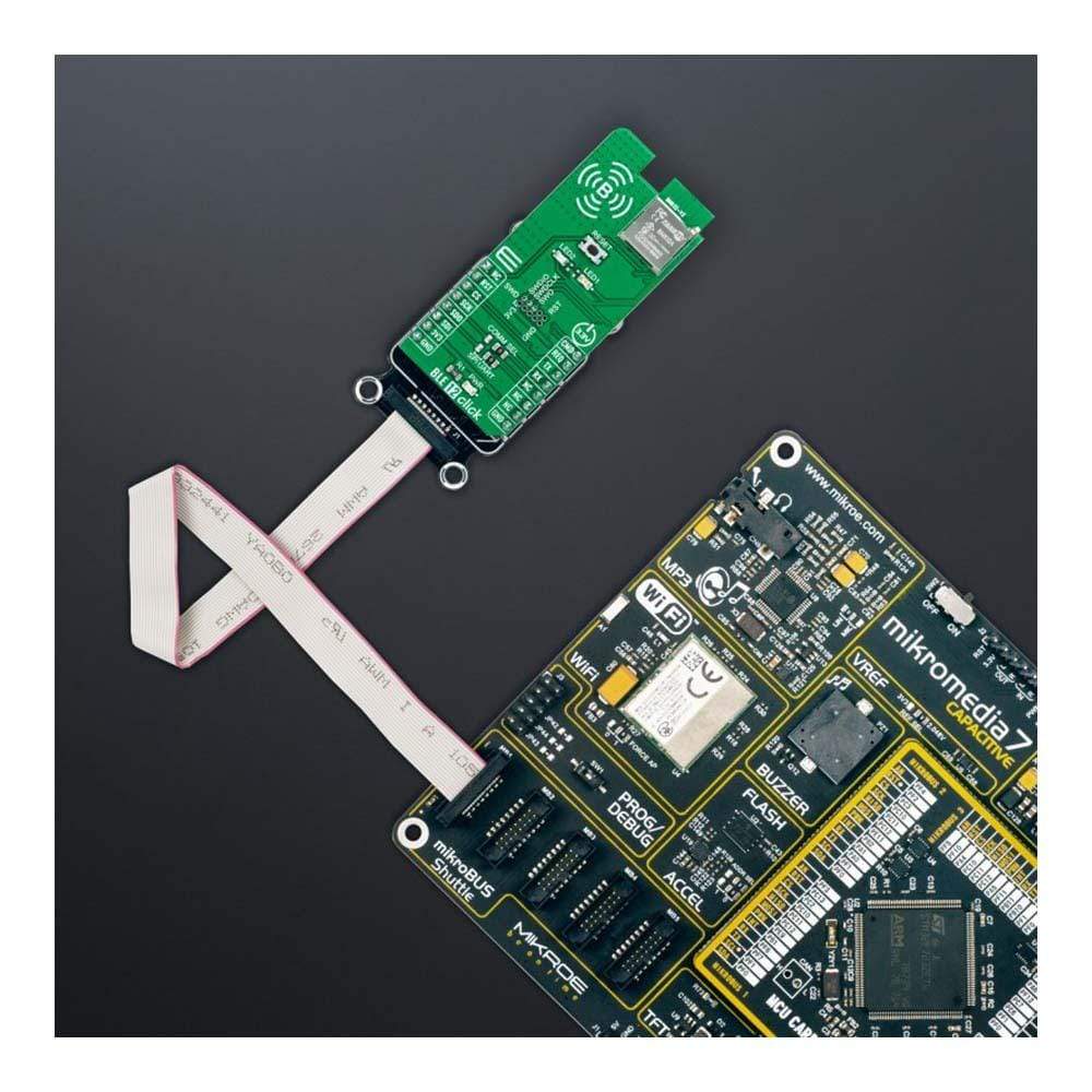
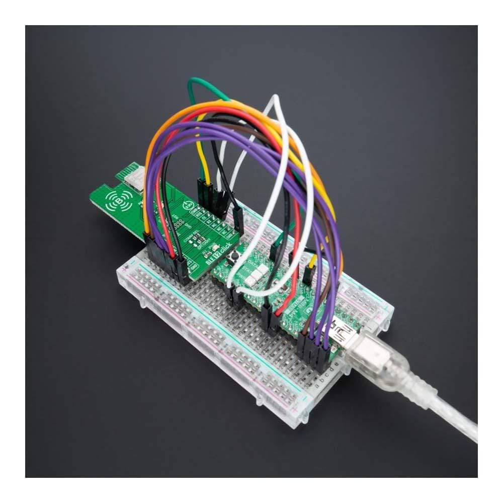
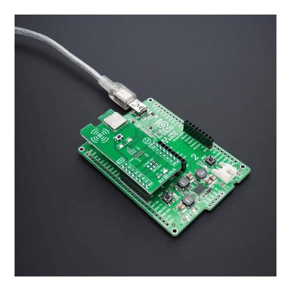
Overview
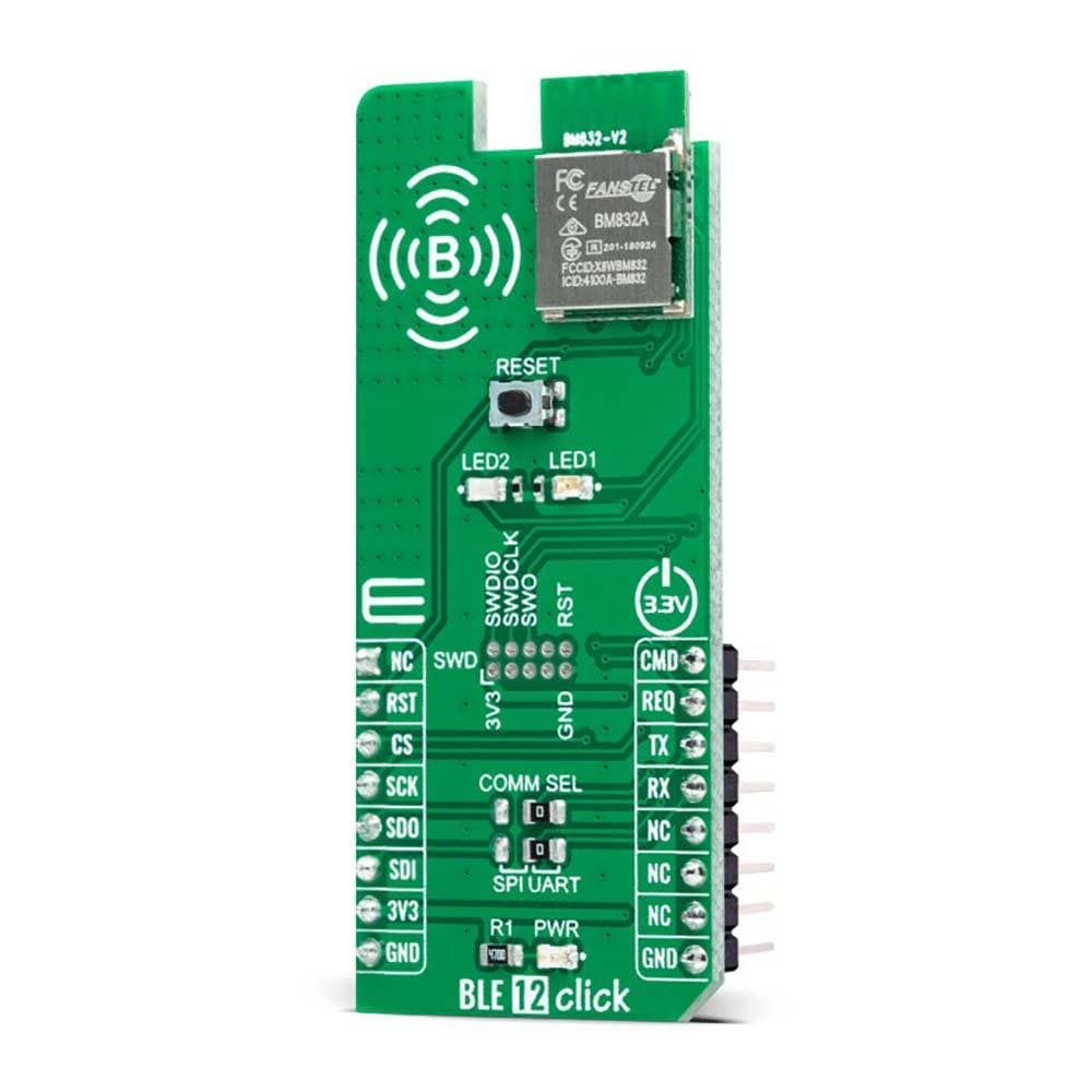
The BLE 12 Click Board™ is a compact add-on board that provides BT/BLE connectivity for any embedded application. This board features the BM832A, a powerful and highly flexible, ultra low power Bluetooth Low Energy (BLE) module from Fanstel. Based on the Nordic nRF52 SoC, the BM832A supports Bluetooth 5.0 Low-Energy (BLE) connectivity while delivering RF range and performance, debugging and enhanced security features, and low power consumption. It also comes with an ARM Cortex™ M4(F) MCU up to 192kB flash and 24kB RAM, an embedded 2.4GHz multi-protocol transceiver, and an integrated PCB trace antenna.
The BLE 12 Click Board™ is suitable for low-cost Bluetooth low energy applications such as building automation and sensor networks, portable medical, connected home, and more.
Downloads
How Does The BLE 12 Click Board™ Work?
The BLE 12 Click Board™ as its foundation uses the BM832A, a highly flexible, ultra low power Bluetooth module that provides BLE connectivity for any embedded application from Fanstel. The BM832A module is based on the Nordic nRF52 SoC, which integrates a 64MHz, 32bit ARM Cortex M4 processor with a floating-point unit (FPU), and a 2.4GHz multiprotocol radio (supporting Bluetooth 5.0, and an integrated PCB trace antenna), featuring -96dBm RX sensitivity (depending on data rate), alongside 192kB Flash memory and 24kB RAM.
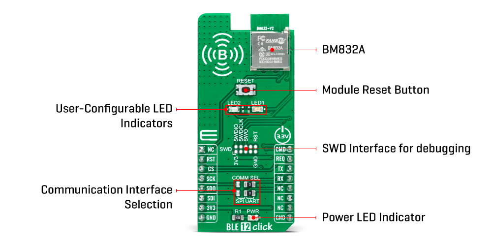
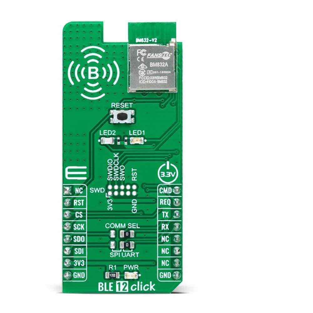
The BLE 12 Click Board™ provides the possibility of using both UART and SPI interfaces, with commonly used UART RX and TX pins as its default communication protocol for exchanging AT commands operating at 115200 bps by default configuration to transmit and exchange data with the host MCU. The selection can be made by positioning SMD jumpers labeled as COMM SEL to an appropriate position. Note that all the jumpers' positions must be on the same side, or the Click board™ may become unresponsive.
The CMD pin routed on the PWM pin of the mikroBUS™ represents the communication-activation feature. A high logic state of the CMD pin allows the module to communicate with the MCU, while a low state allows data to be sent to a far-end device (for example, a smartphone) transparently. With the selected UART interface, power consumption can be reduced by sending the command "AT+STOP". The CS pin needs to be set to a low logic state for 200μs or more to wake up the UART interface. Besides, it has an additional data-ready signal, labeled as REQ and routed on the INT pin of the mikroBUS™ socket, indicating that new data is ready for the host.
The BLE 12 Click Board™ comes with worldwide regulatory certifications and offers enhanced performance, security, and reliability to support IoT products running on Bluetooth networks. Besides, at the center of the BLE 12 Click Board™, an additional unpopulated header offers full support of debugging and programming capabilities. With this header, the user can use a Serial Wire Debug interface for programming and debugging, available through the SWD interface pins (SWDIO, SWCLK, and SWO).
In addition to the appropriate interfaces, the BLE 12 Click Board™ also has some additional features. A Reset button routed to the RST pin on the mikroBUS™ socket puts the module into a Reset state, while the two additional LED indicators, yellow and red LEDs labeled as LED1 and LED2, can be used for optional user-configurable visual indication.
NOTE: To download up-to-date AT command codes for UART and SPI interfaces, the users can visit the official Fanstel website page.
The BLE 12 Click Board™ can be operated only with a 3.3V logic voltage level. The board must perform appropriate logic voltage level conversion before use with MCUs with different logic levels. However, the Click board™ comes equipped with a library containing functions and an example code that can be used, as a reference, for further development.
SPECIFICATIONS
| Type | BT/BLE |
| Applications | The BLE 12 Click Board™ be used for low-cost Bluetooth low energy applications such as building automation and sensor networks, portable medical, connected home, and more |
| On-board modules | BM832A - highly flexible, ultra low power Bluetooth module that provides BLE connectivity for any embedded application from Fanstel Corp |
| Key Features | Bluetooth 5.0 Low-Energy (BLE) solution, complete RF solution with integrated antenna, SWD debug interface, enhanced security features, low power consumption, selectable interface, and more |
| Interface | SPI,UART |
| Compatibility | mikroBUS |
| Click board size | L (57.15 x 25.4 mm) |
| Input Voltage | 3.3V |
PINOUT DIAGRAM
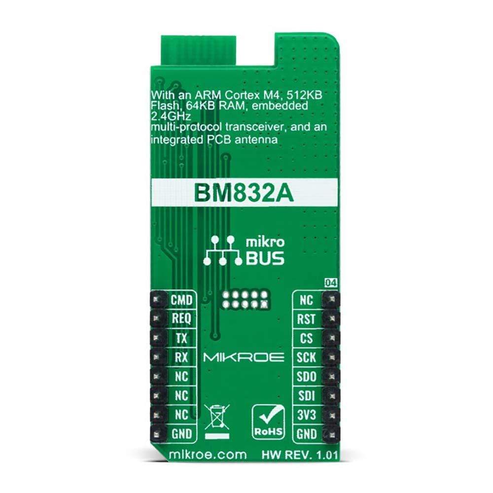
This table shows how the pinout on the BLE 12 Click Board™ corresponds to the pinout on the mikroBUS™ socket (the latter shown in the two middle columns).
| Notes | Pin |  |
Pin | Notes | |||
|---|---|---|---|---|---|---|---|
| NC | 1 | AN | PWM | 16 | CMD | Communication Selection | |
| Reset | RST | 2 | RST | INT | 15 | REQ | Data-Ready |
| SPI Chip Select | CS | 3 | CS | RX | 14 | TX | UART TX |
| SPI Clock | SCK | 4 | SCK | TX | 13 | RX | UART RX |
| SPI Data OUT | SDO | 5 | MISO | SCL | 12 | NC | |
| SPI Data IN | SDI | 6 | MOSI | SDA | 11 | NC | |
| Power Supply | 3.3V | 7 | 3.3V | 5V | 10 | NC | |
| Ground | GND | 8 | GND | GND | 9 | GND | Ground |
ONBOARD SETTINGS AND INDICATORS
| Label | Name | Default | Description |
|---|---|---|---|
| LD1 | PWR | - | Power LED Indicator |
| LD2-LD3 | LED1-LED2 | - | User-Configurable LED Indicators |
| JP1-JP2 | COMM SEL | Right | Communication Interface Selection SPI/UART: Left position SPI, Right position UART |
| J1 | SWD | Unpopulated | SWD Interface Header for Debugging |
BLE 12 CLICK ELECTRICAL SPECIFICATIONS
| Description | Min | Typ | Max | Unit |
|---|---|---|---|---|
| Supply Voltage | - | 3.3 | - | V |
| Operating Range | - | - | 340 | m |
| Frequency Range | - | - | 2.4 | GHz |
| Data Rate | - | - | 1 | Mb/s |
| Sensitivity | - | -96 | - | dBm |
| Memory Size (Flash/RAM) | - | - | 192/24 | kB |
| Operating Temperature Range | -40 | +25 | +85 | °C |
| General Information | |
|---|---|
Part Number (SKU) |
MIKROE-4874
|
Manufacturer |
|
| Physical and Mechanical | |
Weight |
0.02 kg
|
| Other | |
Country of Origin |
|
HS Code Customs Tariff code
|
|
EAN |
8606027384257
|
Warranty |
|
Frequently Asked Questions
Have a Question?
Be the first to ask a question about this.


