
Mikroelektronika d.o.o.
EEPROM 5 Click Board™
EEPROM 5 Click Board™
SKU: MIKROE-4422
Couldn't load pickup availability
Key Features
Overview
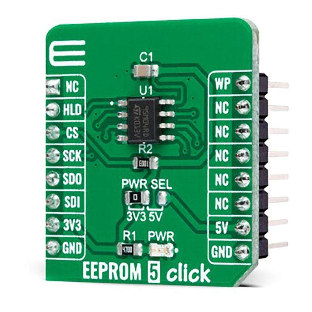
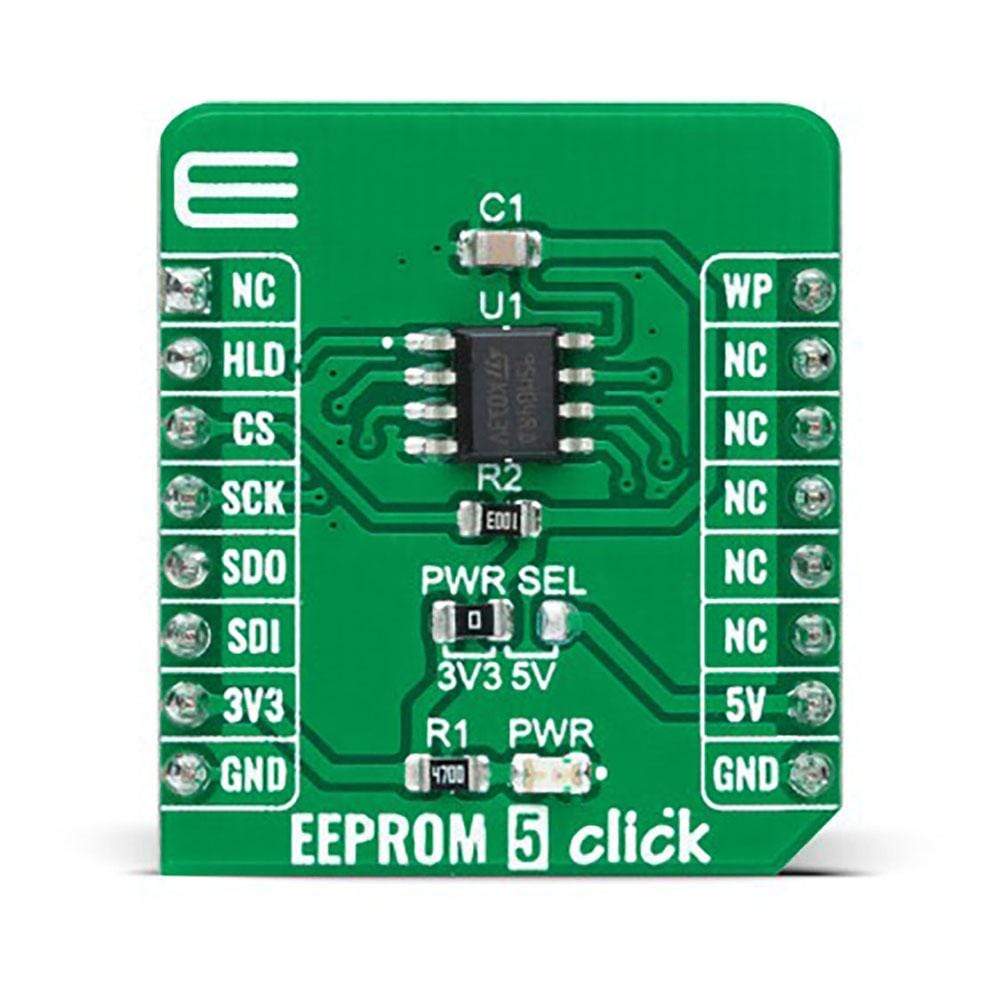
The EEPROM 5 Click Board™ is a compact add-on board that contains the highest-density memory solution. This board features the M95M04, the 4Mbit electrically erasable programmable memory organized as 524288 x 8 bits accessed through the SPI interface from STMicroelectronics. The M95M04 combines unprecedented data storage with excellent energy efficiency. It lasts one billion full-memory read-write cycles with more than 40 years of data retention. It also offers 512-bytes of identification page that can be used to store sensitive application parameters that can be permanently locked in Read-Only mode. This Click Board™ is suitable for a wide range of applications in industrial controls and communication infrastructure where increased memory storage is required.
The EEPROM 5 Click Board™ is supported by a mikroSDK compliant library, which includes functions that simplify software development. This Click Board™ comes as a fully tested product, ready to be used on a system equipped with the mikroBUS™ socket.
Downloads
How Does The EEPROM 5 Click Board™ Work?
The EEPROM 5 Click Board™ is based on the M95M04, the electrically erasable programmable memory organized as 524288 x 8 bits accessed through the SPI interface from STMicroelectronics. The M95M04 benefit from a wide power supply range of 1.8V to 5.5V, as well as 40 years of data retention, and combines their unprecedented data storage with excellent energy efficiency. It is characterized by high reliability, lasting one billion full-memory read-write cycles capable of writing 512 Bytes in 5ms. With 4Mbit capacity, it allows the capture and storage of more data through the serial SPI bus that enables equipment such as smart meters to intensify data logging for managing grids more effectively and providing more user-friendly billing. This Click board™ also provides high-density non-volatile storage for persistent data such as application code, calibration tables, and user parameters, as well as for intensive data logging.
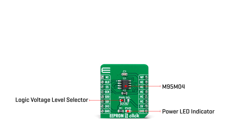
The EEPROM 5 Click Board™ communicates with MCU using the SPI serial interface that supports the two most common modes, SPI Mode 0 and 3, with a maximum SPI frequency of 10 MHz. In addition to the SPI communication, the EEPROM 5 Click also has two additional pins used for Write Protection and HOLD function routed to the PWM and RST pins of the mikroBUS™ socket.
The HOLD pin, labeled as HLD routed to the RST pin of the mikroBUS™ socket, can be used to pause the serial communication with the M95M04 without having to deselect the device. In Normal operation, the M95M04 is kept selected for the whole duration of the Hold condition. Deselecting the device while it is in the HOLD condition has the effect of resetting the device state. On the other side, the configurable Write Protection function, labelled as WP routed to the PWM pin of the mikroBUS™ socket, allows the user to freeze the size of the area of memory that is protected against Write instructions (as specified by the values in the BP1 and BP0 bits of the STATUS register).
The EEPROM 5 Click Board™ is designed to operate with both 3.3V and 5V logic voltage levels selected via the PWR SEL jumper. It allows for both 3.3V and 5V capable MCUs to use the SPI communication lines properly. However, the Click board™ comes equipped with a library that contains easy to use functions and an example code that can be used, as a reference, for further development.
SPECIFICATIONS
| Type | EEPROM |
| Applications | Can be used with persistent data such as application code, calibration tables, and user parameters, as well as for intensive data logging. |
| On-board modules | The EEPROM 5 Click Board™ is based on the M95M04, the electrically erasable programmable memory organized as 524288 x 8 bits accessed through the SPI interface from STMicroelectronics. |
| Key Features | 4 Mbit (512 Kbytes) of EEPROM, write protection, more than 4 million Write cycles, more than 40-year data retention, high reliability, high density, and more. |
| Interface | SPI |
| Compatibility | mikroBUS |
| Click board size | S (28.6 x 25.4 mm) |
| Input Voltage | 3.3V or 5V |
PINOUT DIAGRAM
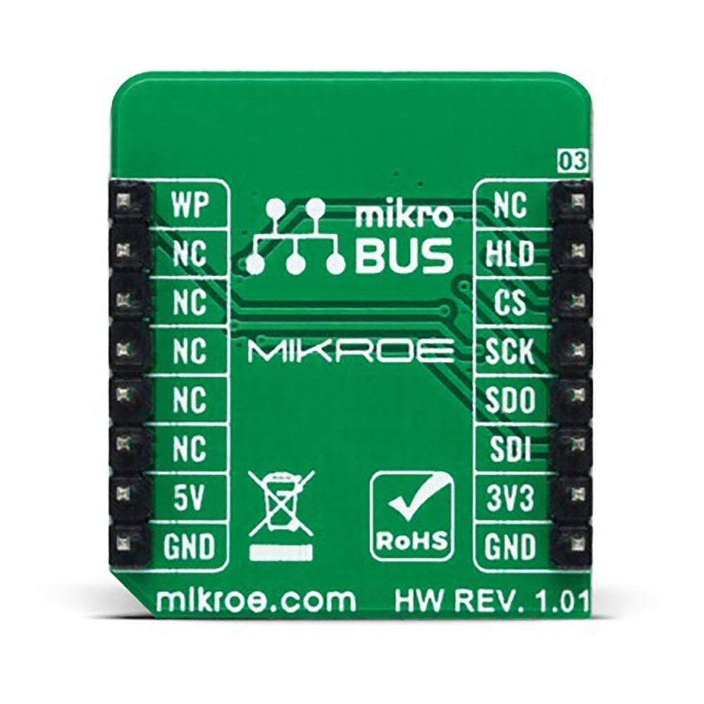
This table shows how the pinout on the EEPROM 5 Click Board™ corresponds to the pinout on the mikroBUS™ socket (the latter shown in the two middle columns).
| Notes | Pin |  |
Pin | Notes | |||
|---|---|---|---|---|---|---|---|
| NC | 1 | AN | PWM | 16 | WP | Write Protect | |
| HOLD Function | HLD | 2 | RST | INT | 15 | NC | |
| SPI Chip Select | CS | 3 | CS | RX | 14 | NC | |
| SPI Clock | SCK | 4 | SCK | TX | 13 | NC | |
| SPI Data OUT | SDO | 5 | MISO | SCL | 12 | NC | |
| SPI Data IN | SDI | 6 | MOSI | SDA | 11 | NC | |
| Power Supply | 3.3V | 7 | 3.3V | 5V | 10 | 5V | Power Supply |
| Ground | GND | 8 | GND | GND | 9 | GND | Ground |
ONBOARD SETTINGS AND INDICATORS
| Label | Name | Default | Description |
|---|---|---|---|
| LD1 | PWR | - | Power LED Indicator |
| JP1 | PWR SEL | Left | Logic Level Voltage Selection 3V3/5V: Left position 3V3, Right position 5V |
EEPROM 5 CLICK ELECTRICAL SPECIFICATIONS
| Description | Min | Typ | Max | Unit |
|---|---|---|---|---|
| Supply Voltage | 1.8 | - | 5.5 | V |
| Maximum Output Current | - | - | 5 | mA |
| Memory Size | - | - | 4096 | kbit |
| EEPROM Write Endurance | - | - | 4000000 | Write Cycles |
| EEPROM Data Retention | 40 | - | - | Years |
| Operating Temperature Range | 40 | - | +85 | °C |
| General Information | |
|---|---|
Part Number (SKU) |
MIKROE-4422
|
Manufacturer |
|
| Physical and Mechanical | |
Weight |
0.016 kg
|
| Other | |
EAN |
8606027381362
|
Frequently Asked Questions
Have a Question?
Be the first to ask a question about this.