


Mikroelektronika d.o.o.
Terminal Click Board™
Terminal Click Board™
SKU: MIKROE-3745
Couldn't load pickup availability

Key Features
Overview
The Ultimate Solution for MikroBus Signal Access: The Terminal Click Board™
Unlock the true potential of your MikroBus signals with the innovative Terminal Click Board™! Whether you're looking to harness the power of I2C or SPI interfaces, this cutting-edge solution is tailor-made for the task.
Why Choose the Terminal Click Board™?
Revolutionize the way you interact with MikroBus signals using our state-of-the-art Terminal Click Board™. With its seamless compatibility, you can seamlessly integrate a Bus Analyzer like the renowned Total Phase Beagle I2C/SPI Sniffer. This means you'll have unparalleled insight into your bus operations, leading to enhanced efficiency and error detection.
Unleash the Power of Connectivity
The Terminal Click Board™ doesn't stop at signal analysis — it's also your gateway to driving Click Board™ Boards from a PC Host Adapter. Imagine the possibilities with the exceptional Total Phase Aardvark or the lightning-fast Cheetah adapter. This combination unlocks new horizons for your projects, offering you the control and versatility you've always craved.
Features at a Glance
- Seamless integration with MikroBus signals
- Full compatibility with I2C and SPI interfaces
- Connectivity with Total Phase Beagle I2C/SPI Sniffer for in-depth analysis
- Empower Click Board™ Boards with PC Host Adapters like Total Phase Aardvark or Cheetah
Upgrade Your Signal Access Today!
Don't miss out on the opportunity to supercharge your MikroBus signal utilization. The Terminal Click Board™ is your ticket to streamlined analysis and unmatched connectivity. Get ready to take your projects to new heights — order your Terminal Click Board™ now!
Downloads
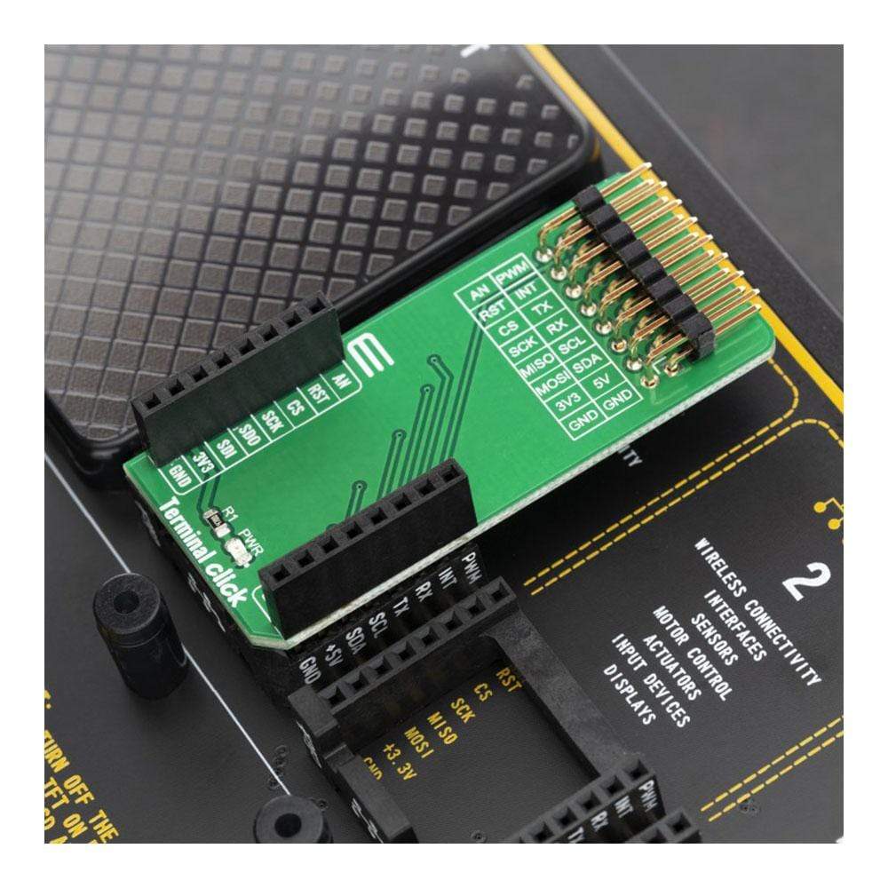
The Terminal Click Board™ can be especially interesting for the development systems that are equipped with mikroBUS™ slots only, or a small number of GPIO pins available, such as the Clicker family of development systems. Using Terminal click on such a system will greatly improve its usability, and yet it will remain small, compact and manageable. Thanks to the standard-pitch (2.54mm) header, it is easy to connect a wire jumper, a probe of an oscilloscope for example, or maybe some additional electronic circuit. That way, Terminal click makes it easy to monitor signals in real-time, while the click board is present in the system.
How Does The Terminal Click Board™ Work?
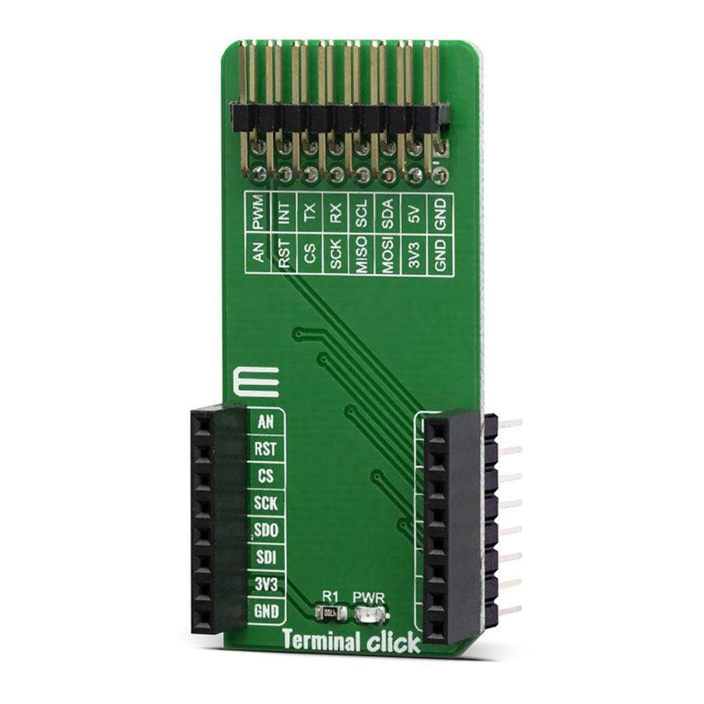
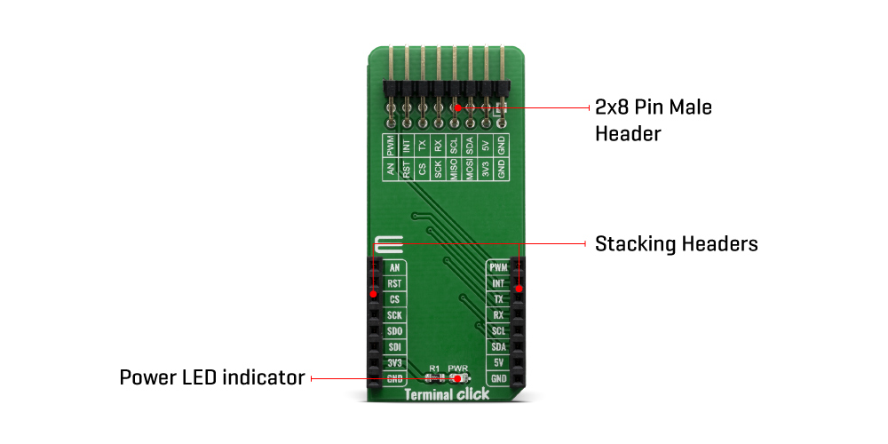
The Terminal Click Board™ consists of a high-quality PCB that can be connected to the mikroBUS™ as any other click board. On the top of the Terminal click, a 2x8 pin header is placed. Each of the header pins is corresponding to a pin on the mikroBUS™ being used. These are simply wired in parallel. Thanks to the stacking headers, the connection with the Click Board™ remain firm and stable. Besides, having this kind of stacking topology, allows for easy pin access and manipulation of the stacked click boards™, retaining a perfect connection quality at all times.
When there's a need to attach external equipment to the development system, the desired mikroBUS™ socket can be populated with Terminal click, allowing even more connections. This makes the stacking capacity almost unlimited. However, attention should be paid not to make the lines attached to the mikroBUS™ too long. In situations like this, the frequency of the communication might need to be stepped down a bit, in order to compensate for the longer mikroBUS™ signal lines.
Lines of the mikroBUS™ to which Terminal click is attached, are shared through the top 16-pin header, which mirrors pins of the connected mikroBUS™. Therefore, care should be taken when working with the Terminal click and connecting an external device to it, because the same pins on the mikroBUS™ are shared, either for the communication (SPI, UART, I2C) or for some other purpose (RST, INT, or other pins used as GPIO).
Since all the stacked click boards™ share the same power rails, a Terminal click also shares the power rails, which makes it compatible with any click board™ and development systems.
Click board™ product range
The union of Terminal click with the other click boards™ allows you to reach an unlimited number of possibilities when it comes to combining different functionalities and adding external connectivity. You just need to choose the ones you want from our ever-growing range: environmental sensors, LEDs, speech recognition, heart rate sensors, motor control, GSM, GPS, WiFi, analogue to digital converters, movement sensors.
More than 1000 Click Boards™ that can be stacked and integrated in a simple and convenient way are at your disposal.
Specifications
| Type | Adapter |
| Applications | Provides easy, secure and reliable stacking of up to four additional boards per mikroBUS™ socket. |
| On-board modules | None |
| Key Features | mikroBUS™ socket expansion board, which provides an easy and elegant solution for adding the external connection capability to the click board™ |
| Interface | GPIO |
| Compatibility | mikroBUS |
| Click board size | L (57.15 x 25.4 mm) |
| Input Voltage | 3.3V,5V |
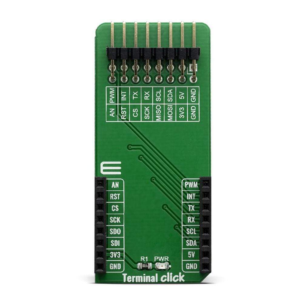
Pinout diagram
This table shows how the pinout on Terminal Click corresponds to the pinout on the mikroBUS™ socket (the latter shown in the two middle columns).
| Notes | Pin | Pin | Notes | ||||
|---|---|---|---|---|---|---|---|
| Analog Input | AN | 1 | AN | PWM | 16 | PWM | PWM Output |
| Reset | RST | 2 | RST | INT | 15 | INT | Hardware Interrupt |
| SPI Chip Enable | CS | 3 | CS | RX | 14 | TX | UART Transmit |
| SPI Clock | SCK | 4 | SCK | TX | 13 | RX | UART Receive |
| SPI Slave Data Out | SDO | 5 | MISO | SCL | 12 | SCL | I2C Clock |
| SPI Slave Data In | SDI | 6 | MOSI | SDA | 11 | SDA | I2C Data |
| Power Supply | 3V3 | 7 | 3.3V | 5V | 10 | 5V | Power Supply |
| Ground | GND | 8 | GND | GND | 9 | GND | Ground |
Onboard settings and indicators
| Label | Name | Default | Description |
|---|---|---|---|
| LD1 | PWR | - | Power LED Indicator |
| J1 | HM2X8 | - | J1 Connector (2.54mm pitch, male header) has 16 pins, one for every mikroBUS™ pin. |
| General Information | |
|---|---|
Part Number (SKU) |
MIKROE-3745
|
Manufacturer |
|
| Physical and Mechanical | |
Weight |
0.021 kg
|
| Other | |
EAN |
8606018716937
|
Frequently Asked Questions
Have a Question?
Be the first to ask a question about this.