


Mikroelektronika d.o.o.
Gyro 4 Click Board™
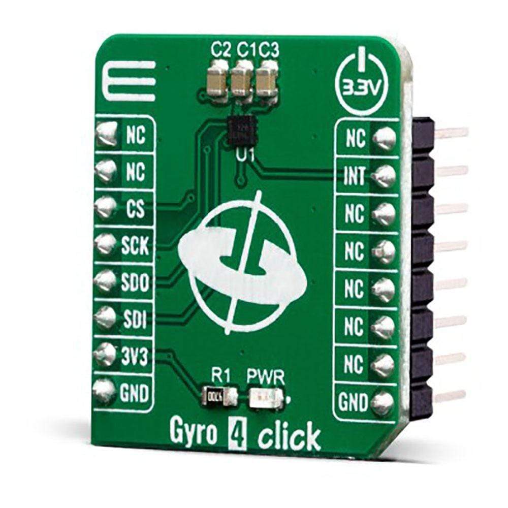
Gyro 4 Click Board™
SKU: MIKROE-3661
Couldn't load pickup availability


Overview
The Gyro 4 Click Board™ is a two-axis MEMS gyroscope for optical image stabilization applications. It is equipped with the L20G20IS, that includes a sensing element and an IC interface capable of providing the measured angular rate to the application through an SPI digital interface. The angular data is available in a 16-bit format, along with 12-bit device’s die temperature data. The IC interface is manufactured using a CMOS process that allows a high level of integration to design a dedicated circuit which is trimmed to better match the characteristics of the sensing element.
Downloads
The L20G20IS IC supports SPI interface which allows the Gyro 4 Click Board™ to be interfaced with a wide range of different MCUs. The IC interface is manufactured using a CMOS process that allows a high level of integration to design a dedicated circuit which is trimmed to better match the characteristics of the sensing element. It's perfect solution for optical image stabilization applications.
How Does The Gyro 4 Click Board™ Work?
The Gyro 4 Click Board™ features L20G20IS two-axis MEMS gyroscope, from ST microelectronics. An angular rate gyroscope is a device that produces a positive-going digital output for counterclockwise rotation around the sensitive axis considered. Sensitivity describes the gain of the sensor and can be determined by applying a defined angular velocity to it. This value changes very little over temperature and time.
.jpg)
The zero-rate level describes the actual output signal if there is no angular rate present. The zero-rate level of highly accurate MEMS sensors is, to some extent, a result of stress to the sensor and therefore the zero-rate level can slightly change after mounting the sensor on a printed circuit board or after exposing it to extensive mechanical stress. This value changes very little over temperature and time. The L20G20IS includes temperature sensor and data can be retrieved from the registers, as two's complement data in 12-bit format left-justified. The output of the temperature sensor is 0 at 25 °C.
On the L20G20IS the angular rate data can be retrieved using a synchronous read. To perform a synchronous read, CTRL4_OIS (0Eh R/W) (DRDY_EN) has to be set to '1' in order to enable the data-ready interrupt on the INT pin. To properly perform a synchronous read, the angular rate data have to be read every time the DRDY pin goes high. The INT signal can be latched (default condition) or pulsed.
When a latched condition is selected, the interrupt goes low when the high part of one of the output channels is read and returns high when new data is generated. When a pulsed condition is selected, the interrupt behavior is independent from the read operations and remains high for 75 µs every time new data is generated. The INT pin is set by default as push-pull output, but it can be configured as open-drain output.
SPECIFICATIONS
| Type | Gyroscope,Motion |
| Applications | The Gyro 4 Click Board™ can be used to develop optical image stabilization or some similar applications. |
| On-board modules | L20G20IS, is a two-axis MEMS gyroscope sensor IC, by STMicroelectronics |
| Key Features | Integrated low-pass filters with user-selectable bandwidth, ±100 dps / ±200 dps full-scale range,embedded self-test… |
| Interface | SPI |
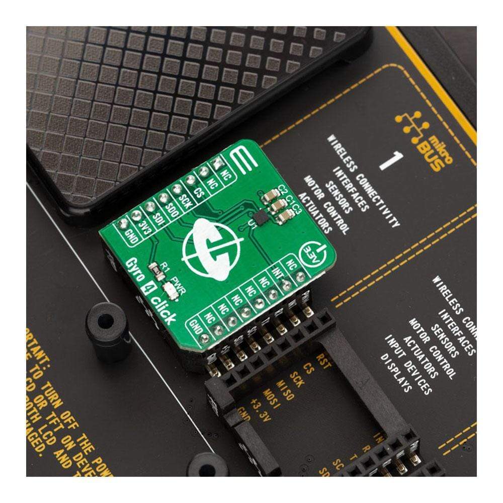
| Compatibility | mikroBUS |
| Click board size | S (28.6 x 25.4 mm) |
| Input Voltage | 3.3V |
PINOUT DIAGRAM
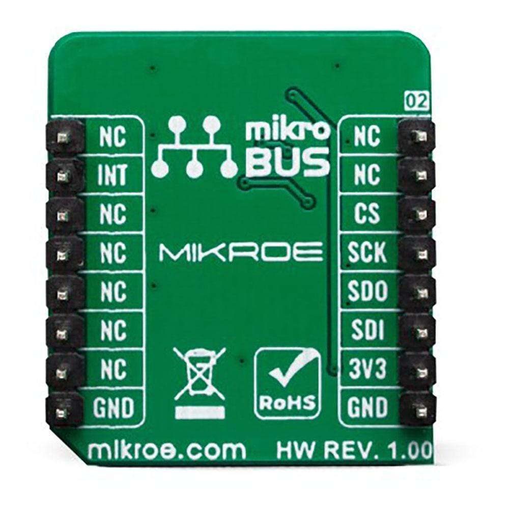
This table shows how the pinout of the Gyro 4 Click Board™ corresponds to the pinout on the mikroBUS™ socket (the latter shown in the two middle columns).
| Notes | Pin | Pin | Notes | ||||
|---|---|---|---|---|---|---|---|
| NC | 1 | AN | PWM | 16 | NC | ||
| NC | 2 | RST | INT | 15 | INT | INTERRUPT | |
| SPI Chip Select | CS | 3 | CS | RX | 14 | NC | |
| SPI Clock | SCK | 4 | SCK | TX | 13 | NC | |
| SPI Data OUT | SDO | 5 | MISO | SCL | 12 | NC | |
| SPI Data IN | SDI | 6 | MOSI | SDA | 11 | NC | |
| Power Supply | 3.3V | 7 | 3.3V | 5V | 10 | NC | |
| Ground | GND | 8 | GND | GND | 9 | GND | Ground |
ONBOARD SETTINGS AND INDICATORS
| Label | Name | Default | Description |
|---|---|---|---|
| LD1 | PWR | - | Power LED Indicator |
| General Information | |
|---|---|
Part Number (SKU) |
MIKROE-3661
|
Manufacturer |
|
| Physical and Mechanical | |
Weight |
0.017 kg
|
| Other | |
EAN |
8606018716449
|
Frequently Asked Questions
Have a Question?
Be the first to ask a question about this.