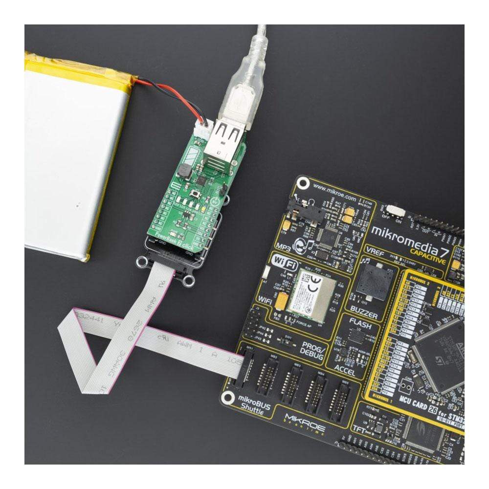
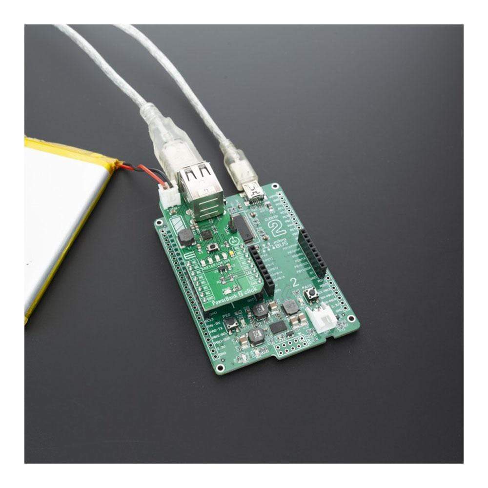
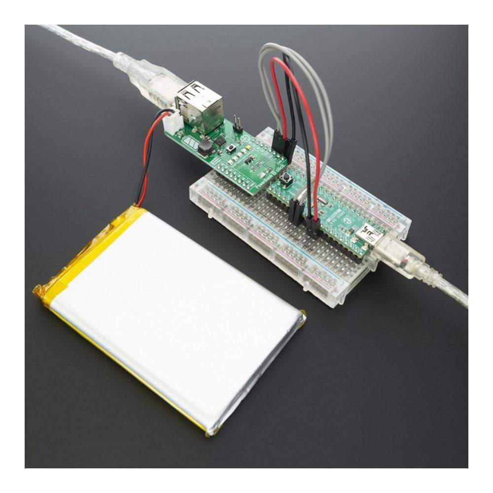
PowerBank 2 Click-Platine
Overview
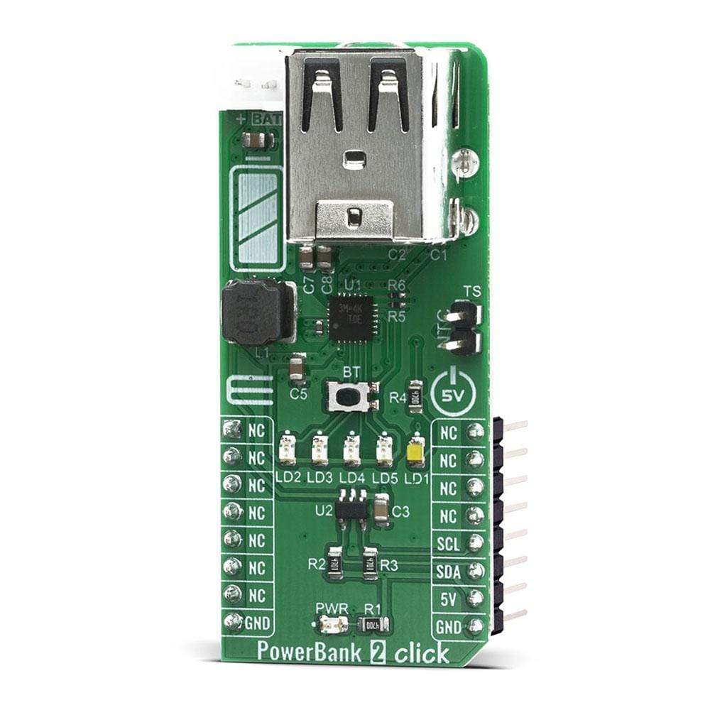
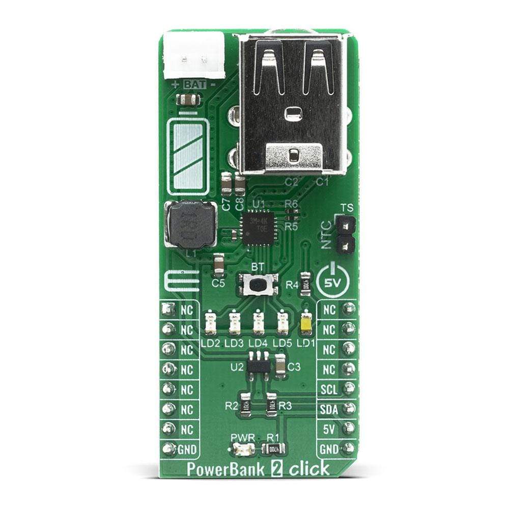
Das PowerBank 2 Click Board ™ ist mit dem RT9480 ausgestattet, einer hochintegrierten und einfach zu bedienenden Stromversorgungslösung für Li-Ionen-Powerbanks und andere strombetriebene Handheld-Anwendungen. Es wird üblicherweise als EZPBS (Easy to Use PowerBank Solution) bezeichnet. Dieser Single-Chip enthält ein lineares Ladegerät, einen synchronen Boost mit Dual-Output-Lastmanagement und eine Taschenlampenfunktionsunterstützung. Das Batterievolumen und der Lade- und Entladezustand können durch 4 LEDs angezeigt werden.
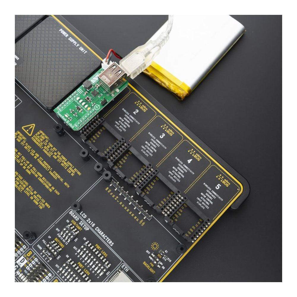
PowerBank 2 Click wird von einer mikroSDK-kompatiblen Bibliothek unterstützt, die Funktionen enthält, die die Softwareentwicklung vereinfachen. Dieses Click Board™ wird als vollständig getestetes Produkt geliefert und ist bereit für den Einsatz auf einem System, das mit der mikroBUS™-Buchse ausgestattet ist.
How Does The PowerBank 2 Click Board™ Work?
The RT9480 is a high integrated IC for Li-Ion battery power bank. It includes a linear charger 1.2A, a synchronous Boost 5.1V, two output load management, LED indicator and torch function. Based on thermal regulation function, the charging current can support up to 1.2A If the input voltage (VBUS) is higher than the threshold voltage VOVP , the internal OVP signal will go high and the charger will stop charging until VIN is below VOVP − ΔVOVP and if the internal voltage (VMID) is higher than the threshold voltage VOVP, the internal OVP signal will go high and the charger will stop charging until VMID is below VOVP − ΔVOVP.
The converter senses the current signal when the high-side P-MOSFET turns on. As a result, The OCP is cycle by-cycle current limitation. If the OCP occurs, the converter holds off the next on pulse until inductor current drops below the OCP limit. It also has an over-temperature protection. When the junction temperature is higher than the thermal shutdown rising threshold, the system will be latched and the output voltage will no longer be regulated until the junction temperature drops under the falling threshold. In a case of output short to ground, the system will be latched and the output voltage will no longer be regulated until power reset.
There are constant current loop, constant voltage loop and thermal regulation loop to control the charging current. The temperature sense input TS pin can be connected a thermistor to determine whether the battery is too hot or too cold for charging operation. If the battery's temperature is out of range, charging is paused until it re-enters the valid range.
A 4-LEDs indicate attery volume and the state of charging and discharging. Together with torch-light control, the RT9480 provides an all-in-one solution for power banks and similar applications without an external microcontroller. Detailed information about LED indicators can be found in RT9480 datasheet.
The PowerBank 2 Click Board™ is also equipped with a MCP3221, a successive approximation A/D converter (ADC) with a 12-bit resolution to monitor battery voltage over I2C bus over mikroBUS™ socket.
This Click Board™ is designed to be operated only with 5V logic level. A proper logic voltage level conversion should be performed before the Click board™ is used with MCUs with logic levels of 3V3.
SPECIFICATIONS
Type | Optical |
Applications | Sub-Battery Applications, Power-Bank Applications for Smartphones, Tablets and Other Portable Devices |
On-board modules | RT9480 |
Key Features | Power solution for Li-ion power bank and other powered handheld applications, a synchronous Boost with dual output load management and a torch function support, designed for single-cell Li-ion or Li-polymer batteries |
Interface | I2C |
Compatibility | mikroBUS |
Click board size | L (57.15 x 25.4 mm) |
Input Voltage | 5V |
PINOUT DIAGRAM
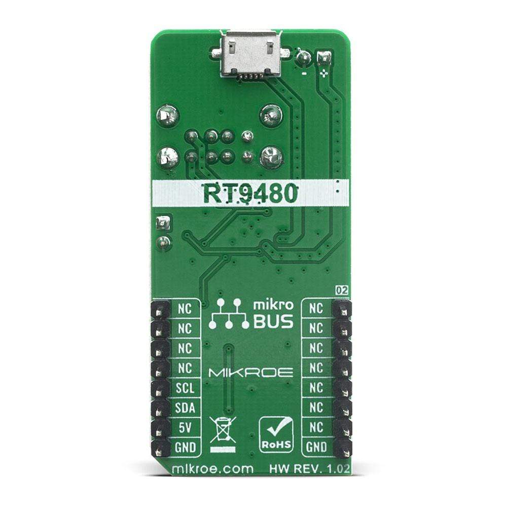
This table shows how the pinout on PowerBank 2 Click corresponds to the pinout on the mikroBUS™ socket (the latter shown in the two middle columns).
Notes | Pin | Pin | Notes | ||||
---|---|---|---|---|---|---|---|
NC | 1 | AN | PWM | 16 | NC | ||
NC | 2 | RST | INT | 15 | NC | ||
NC | 3 | CS | RX | 14 | NC | ||
NC | 4 | SCK | TX | 13 | NC | ||
NC | 5 | MISO | SCL | 12 | SCL | I2C Clock | |
NC | 6 | MOSI | SDA | 11 | SDA | I2C Data | |
NC | 7 | 3.3V | 5V | 10 | 5V | Power Supply | |
Ground | GND | 8 | GND | GND | 9 | GND | Ground |
ONBOARD SETTINGS AND INDICATORS
Label | Name | Default | Description |
---|---|---|---|
PWR | PWR | - | Power LED Indicator |
LD2-5 | LD2-5 | - | Battery Status LEDs |
LD1 | LD1 | - | Torch LED |
BT | - | - | Operation Mode Selector |
CN1 | - | - | USB Power |
CN2 | - | - | USB Charge Port |
We provide a library for the PowerBank2 Click on our LibStock page, as well as a demo application (example), developed using MikroElektronika compilers. The demo can run on all the main MikroElektronika development boards.
Library Description
The library covers all the necessary functions that enables the usage of the PowerBank 2 click board. It offers reading from output register and calculations that result in relatively accurate measurement of connected batteries voltage.
Key Functions
uint16_t powerbank2_read_data ( );
- Function is used to read raw data from MCP3221.uint16_t powerbank2_read_voltage ( uint16_t v_ref );
- Function is used to calculate voltage of the connected battery.
Example Description
The application is composed of three sections :
- System Initialization - Initializes I2C module and LOG structure.
- Application Initialization - Initalizes I2C driver and makes an initial log.
- Application Task - This example shows the capabilities of the Power Bank 2 click by measuring voltage of the connected battery. In order to get correct calculations user should change "v_ref" value to his own power supply voltage.
void application_task ( ) { voltage = powerbank2_read_voltage( v_ref ); WordToStr( voltage, log_txt ); mikrobus_logWrite( "Battery voltage: ", _LOG_TEXT ); mikrobus_logWrite( log_txt, _LOG_TEXT ); mikrobus_logWrite( "mV", _LOG_LINE ); mikrobus_logWrite( "------------------------", _LOG_LINE ); Delay_ms( 2000 ); }
The full application code, and ready to use projects can be found on our LibStock page.
Other mikroE Libraries used in the example:
- I2C
- UART
- Conversions
Additional Notes and Information
Depending on the development board you are using, you may need USB UART click, USB UART 2 click or RS232 click to connect to your PC, for development systems with no UART to USB interface available on the board. The terminal available in all MikroElektronika compilers, or any other terminal application of your choice, can be used to read the message.
MIKROSDK
This Click board™ is supported with mikroSDK - MikroElektronika Software Development Kit. To ensure proper operation of mikroSDK compliant Click board™ demo applications, mikroSDK should be downloaded from the LibStock and installed for the compiler you are using.
Frequently Asked Questions
Have a Question?
Be the first to ask a question about this.