Power/Reset-Click-Platine
Overview
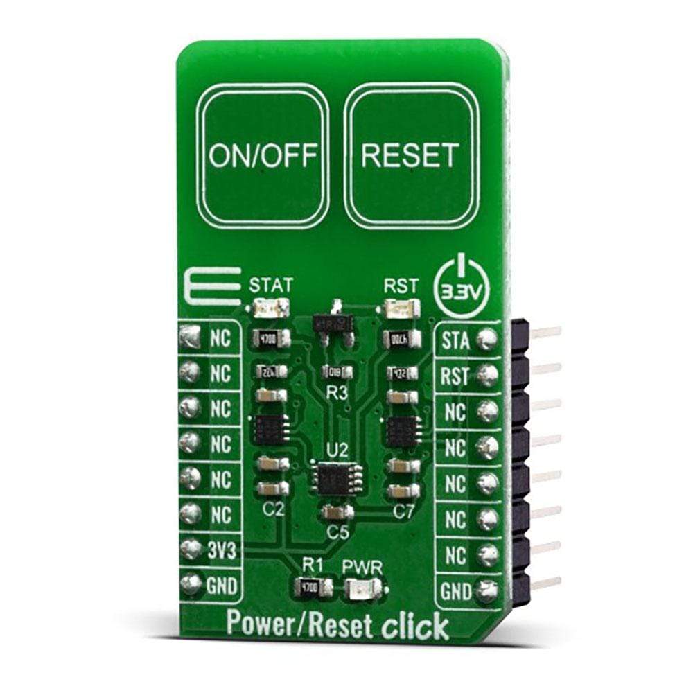
Der Ein-/Ausschalten/Reset von Click Board™ ist mit zwei kapazitiven Touchpads auf einem Single Click Board™ ausgestattet. Es kann durch Berühren aktiviert werden und im Gegensatz zu mechanischen Tasten hält die kapazitive Touch-Taste viel länger, ist nicht anfällig für Beschädigungen und Verschleiß und sehr zuverlässig. Kapazitive Tasten sind eine sehr beliebte Methode zum Einschalten oder Zurücksetzen verschiedener Geräte. Neben den oben genannten Vorteilen ermöglicht eine berührungsempfindliche Taste an einem Gerät ein kompaktes Design, eröffnet Möglichkeiten für verschiedene Arten von Mensch-Maschine-Schnittstellen und sieht gut und modern aus, insbesondere wenn sie von einer LED begleitet wird, die bei Aktivierung aufleuchtet, genau wie die bei Power/Reset Click.
Das Power/Reset Click Board™ findet in vielen Anwendungen seinen Einsatz – für berührungsaktivierte Lichtsteuerungen, berührungsaktivierte Bedienfelder, Spielzeuge und alle anderen Anwendungen, die einen Schalter oder eine Taste zum Einschalten und Zurücksetzen eines Geräts benötigen.
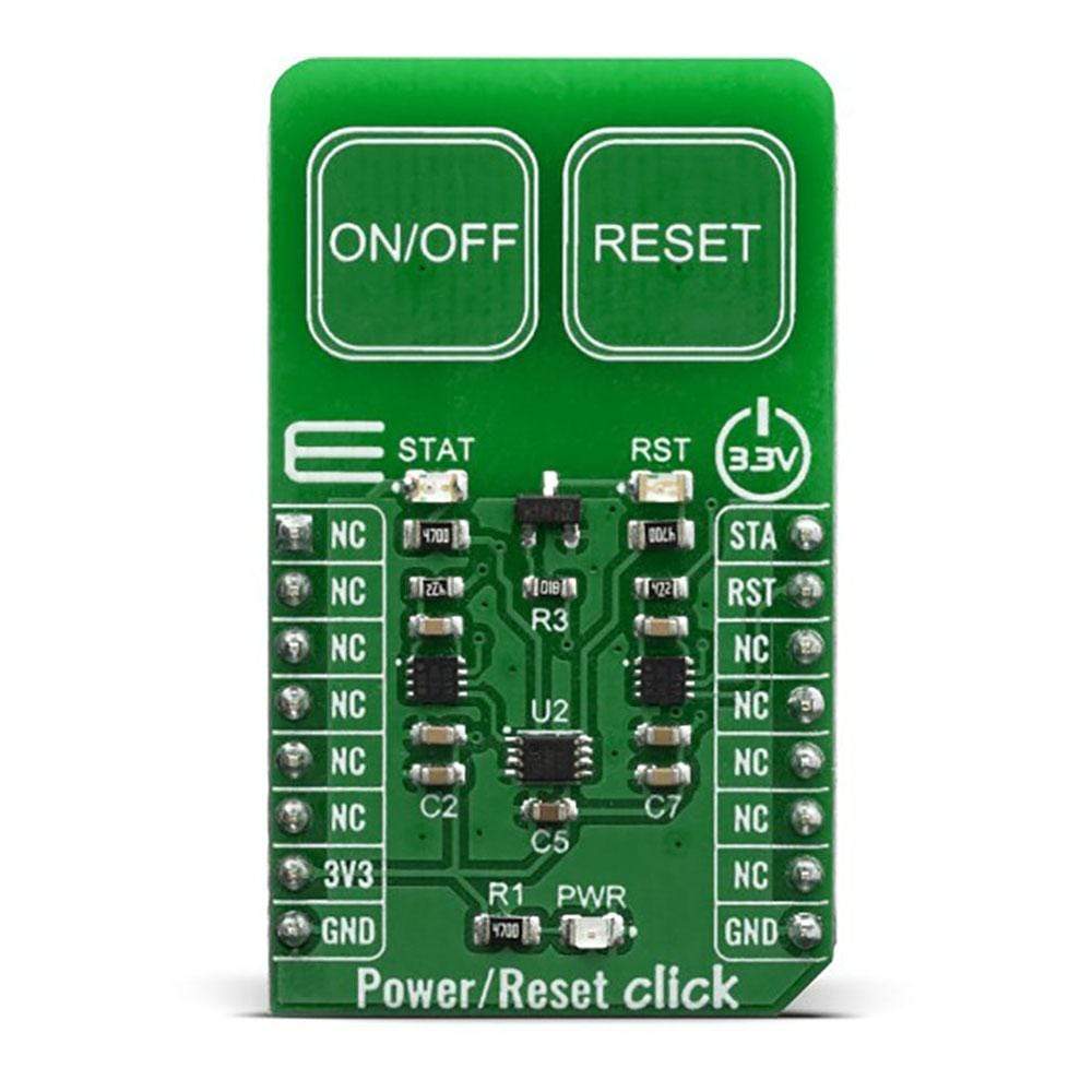
The Power/Reset Click Board™ has two PCB pads, used to sense touch or proximity events. These pads are the only elements on the top of the board, allowing installation of the protective acrylic glass layer. These pads are marked as ON/OFF and RESET in order to offer to a user a simple solution for a capacitive switching power and reset controls for various devices. This click board™ includes all hardware and signal processing functions necessary to provide stable sensing under a wide variety of changing conditions.
How Does The Power/Reset Click Board™ Work?
The Power/Reset Click Board™ is a capacitive touch sensing Click board™ which features the QT1011, digital burst mode charge-transfer sensor that is capable of detecting near proximity or touch, from Microchip. This click board™ has two PCB pads, used to sense touch or proximity events. Besides the two touch sensitive pads, Power/Reset click has two LED diodes for the touch indication. The two touch pads use two separate QT1011 ICs, providing a very reliable touch sensing functionality.
The AT42QT1011 is a digital burst mode charge-transfer sensor that is capable of detecting nearproximity or touch, making it ideal for implementing touch controls. With the proper electrode and circuit design, the self-contained digital IC will project a touch or proximity field to several centimeters through any dielectric like glass, plastic, stone, ceramic, and even most kinds of wood. It can also turn small metal-bearing objects into intrinsic sensors, making them responsive to proximity or touch. This capability, coupled with its ability to self-calibrate, can lead to entirely new product concepts.
The QT1011 is designed specifically for human interfaces like control panels, appliances, toys, lighting controls, or anywhere a mechanical switch or button may be found. It includes all hardware and signal processing functions necessary to provide stable sensing under a wide variety of changing conditions. However, this click board™ is designed to serve as a power and reset capacitive switch panel board.
Besides the QT1011, the Power/Reset Click Board™ contains 74LVC1G74 as well. It is a Single D-type flip-flop with set and reset. Because The output of the QT1011 is active-high upon detection, the 74LVC1G74 is triggered by the positive edge of the ON/OFF touch pad. It is wired in a cascade with the QT1011 in way that ensures holding one logical state until the ON/OFF pad is pressed. Therefore, the ON/OFF pad acts like a switch, while the RESET pad acts like a button, which is suitable for most common purposes.
The output signals for the ON/OFF and RESET pads are wired to the PWM and INT pins on the mikroBUS™, respectively. Besides that, the STAT and RST LEDs are wired parallel to the outputs in order to ensure a visible indication of the status of the pins.
The Power/Reset Click Board™ is designed to be operated only with 3.3V logic level. A proper logic voltage level conversion should be performed before the Click board™ is used with MCUs with logic levels of 5V.
SPECIFICATIONS
Type | Capacitive |
Applications | Touch activated lighting controls, touch activated control panels, toys and any other applications that need a switch or a button for powering and resetting a device. |
On-board modules | QT1011, digital burst mode charge-transfer sensor that is capable of detecting near proximity or touch, from Microchip. |
Key Features | Reliable capacitive touch detection technology, noise filtering, Patented spread-spectrum charge-transfer (direct mode), Increased moisture tolerance |
Interface | GPIO |
Compatibility | mikroBUS |
Click board size | M (42.9 x 25.4 mm) |
Input Voltage | 3.3V |
PINOUT DIAGRAM
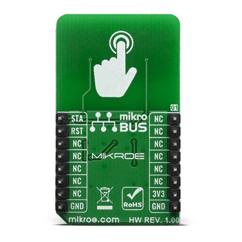
This table shows how the pinout on Power/Reset Click corresponds to the pinout on the mikroBUS™ socket (the latter shown in the two middle columns).
Notes | Pin | Pin | Notes | ||||
---|---|---|---|---|---|---|---|
NC | 1 | AN | PWM | 16 | STA | ON/OFF Status Out | |
NC | 2 | RST | INT | 15 | RST | Reset Out | |
NC | 3 | CS | RX | 14 | NC | ||
NC | 4 | SCK | TX | 13 | NC | ||
NC | 5 | MISO | SCL | 12 | NC | ||
NC | 6 | MOSI | SDA | 11 | NC | ||
Power Supply | 3.3V | 7 | 3.3V | 5V | 10 | NC | |
Ground | GND | 8 | GND | GND | 9 | GND | Ground |
ONBOARD SETTINGS AND INDICATORS
Label | Name | Default | Description |
---|---|---|---|
LD1 | STAT | - | ON/OFF Status Out |
LD2 | PWR | - | Power LED Indicator |
LD3 | RST | - | RESET Status |
We provide a library for the Power/Reset Click Board™ on our LibStock page, as well as a demo application (example), developed using MikroElektronika compilers. The demo can run on all the main MikroElektronika development boards.
Library Description
This library allows user to check which button is pressed or activated. Also initializes GPIO driver. For more details check documentation.
Key Functions
void touchbutt_gpioDriverInit(T_TOUCHBUTT_P gpioObj)
- This function initializes GPIO driver.T_TOUCHBUTT_STATE touchbutt_getPWR( void )
- This function returns a state of the PWR pin (ON/OFF button).T_TOUCHBUTT_STATE touchbutt_getRST( void )
- This function returns a state of the RST pin (RESET button).
Example Description
The application is composed of three sections :
- System Initialization - Initializes peripherals and pins.
- Application Initialization - Initializes GPIO driver and performs a timer interrupt configuration.
- Application Task - (code snippet) - Checks the states of the PWR and RST pins and performs a control of the timer counter depending on the pressed button (pins state). User can start and stop a timer counter, in the resolution of 100ms, by pressing the ON/OFF button. Also can reset a timer counter to 0 by pressing the RESET button. When timer counter was reached the target time (in seconds), a message will be sent to the uart terminal and the sound will be generated. Timer counter state will be showed to the uart terminal.
void applicationTask() { pwr_state = touchbutt_getPWR(); rst_state = touchbutt_getRST(); if ((pwr_state == _TOUCHBUTT_ACTIVE) && (time_cnt_prev != time_cnt) && (rst_state == _TOUCHBUTT_INACTIVE)) { time_val_dec = time_cnt / 10; time_val_real = time_cnt % 10; LongWordToStr( time_val_dec, text ); Ltrim( text ); mikrobus_logWrite( text, _LOG_TEXT ); mikrobus_logWrite( ".", _LOG_TEXT ); ByteToStr( time_val_real, text ); Ltrim( text ); mikrobus_logWrite( text, _LOG_LINE ); if ((time_val_dec >= target_time) && (alarm_flag == _TOUCHBUTT_ACTIVE)) { mikrobus_logWrite( "** Target time is reached! **", _LOG_LINE ); alarm_flag = _TOUCHBUTT_INACTIVE; Sound_Play( 1000, 50 ); Delay_ms( 40 ); Sound_Play( 1000, 50 ); Delay_ms( 40 ); } } if (rst_state == _TOUCHBUTT_ACTIVE) { time_cnt = 0; alarm_flag = _TOUCHBUTT_ACTIVE; } else { time_cnt_prev = time_cnt; } }
The full application code, and ready to use projects can be found on our LibStock page.
Other mikroE Libraries used in the example:
- Conversions
- C_String
- Sound
- UART
Additional Notes and Information
Depending on the development board you are using, you may need a USB UART click, USB UART 2 click or RS232 click to connect to your PC, for development systems with no UART to USB interface available on the board. The terminal available in all MikroElektronika compilers, or any other terminal application of your choice, can be used to read the message.
MIKROSDK
The Power/Reset Click Board™ is supported with mikroSDK - MikroElektronika Software Development Kit. To ensure proper operation of mikroSDK compliant Click board™ demo applications, mikroSDK should be downloaded from the LibStock and installed for the compiler you are using.
Frequently Asked Questions
Have a Question?
Be the first to ask a question about this.