Mikroelektronika d.o.o.
Erweitern Sie das Click Board
Erweitern Sie das Click Board
Verfügbarkeit für Abholungen konnte nicht geladen werden
Key Features
- Kann mit einem 3,3- oder 5-V-Netzteil verwendet werden
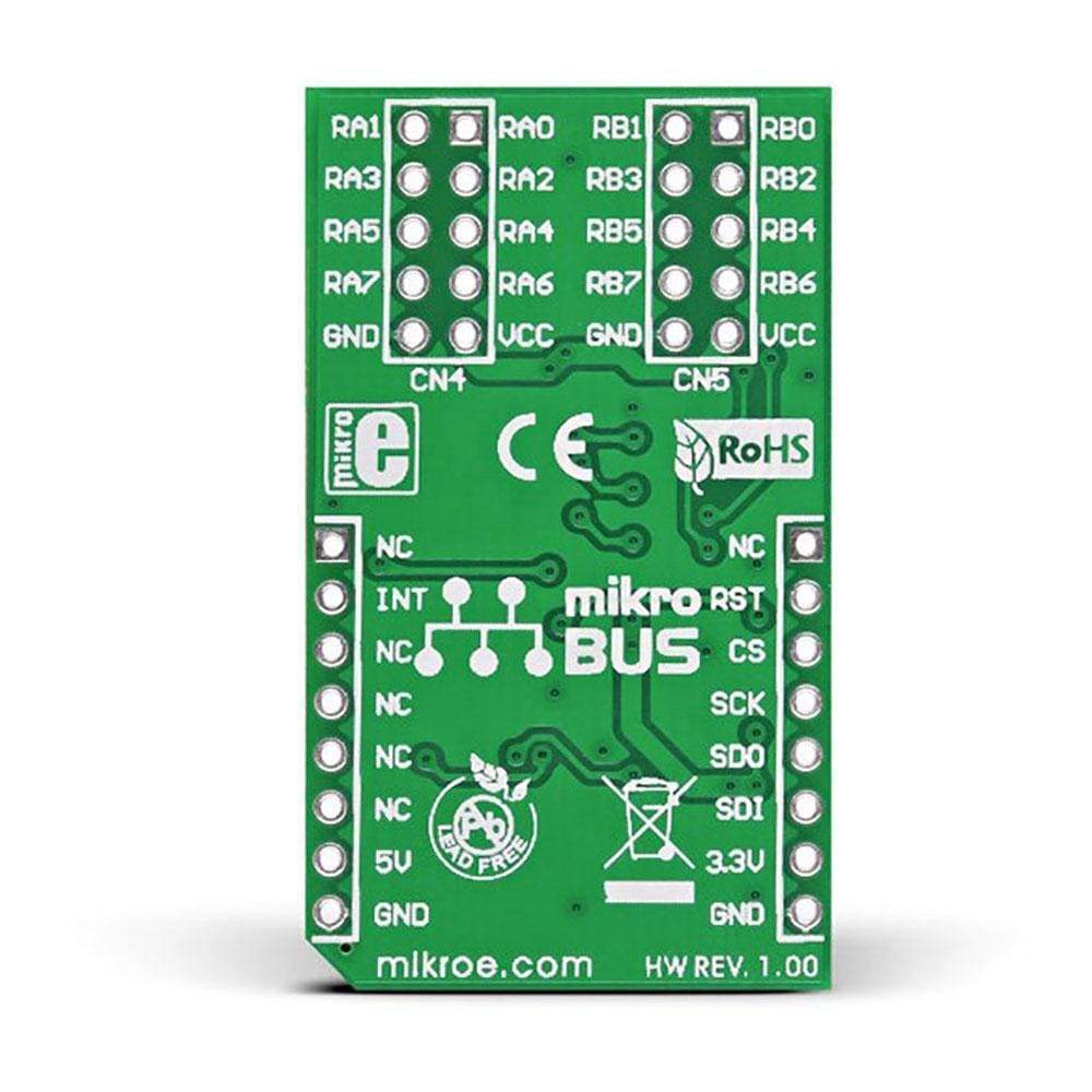
- mikroBUS: SPI-Schnittstelle
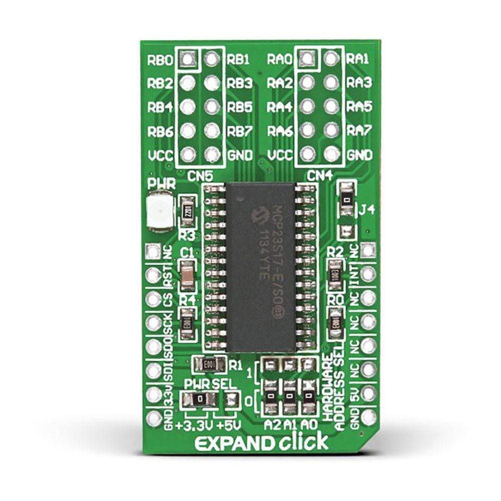
Das Expand Click Board™ ist eine Zubehörplatine im MikroBUS-Formfaktor. Es enthält einen 16-Bit-E/A-Expander MCP23S17 von Microchip mit SPI-Taktraten von bis zu 10 MHz für Anwendungen mit höherem Durchsatz.


The Expand Click Board™ is an add-on board featuring a Microchip MCP23S17 16-bit I/O expander with SPI clock speeds up to 10 MHz for higher rate of production of applications. For board address configuration, it uses three HARDWARE ADDRESS SEL jumpers that also allows for connection with up to eight devices on the bus. The interrupt-on-change feature is also supported by the controller. EXPAND Click Board™ uses the SPI communication interface for communication with the on-board port expander. The 16 bidirectional I/O port bits are divided into two 8-bit ports (PORTA and PORTB). The user can choose to configure MCP23S17 to operate in the 8-bit or 16-bit mode. Acting as bidirectional I/Os, all the pins can be enabled for internal weak pull-up resistor and/or interrupt-on-change.
With these features, this board is an ideal choice for saving microcontroller pins, and expanding the number of input-output lines. EXPAND Click Board™ is designed to use a 3.3V power supply in the default position. For use with 5V systems, solder the PWR SEL SMD jumper to 5V position.
Note: For using I2C instead of SPI, check out the Expand 2 Click Board™ using the MCP23S17 IC.
IC/Module: MCP23S17 16-Bit I/O Expander
The MCP23S17 is a 16-bit I/O expander that supports up to 10MHz SPI clock speeds. It consists of multiple 8-bit configuration registers for input, output and polarity selection. The system master can enable the I/Os as either inputs or outputs by writing the I/O configuration bits (IODIRA/B). Consisting of two 8-bit ports, MCP23S17 module can be operated in the 8-bit or 16-bit modes.
SMD Jumpers
EXPAND Click Board™ features four on-board zero-ohm SMD jumpers, which includes three HARDWARE ADDRESS SEL for choosing the device address, and a PWR SEL jumper that enable the user to switch from 3.3V to 5V power supply.
Software Support
Application Task
This is an example that demonstrates the use of Expand Click board. Expand Click communicates with register via SPI protocol by write and read from the register, set configuration and state and read configuration and state. Results are being sent to the Usart Terminal where you can track their changes. All data logs on USB uart for approximately every 500 ms.
void application_task ( void )
{
    pin_position = 1;

    for ( position = 0; position < 8; position++ )
    {
        expand_write_port_a( &expand, EXPAND_SPI_MODULE_POSITION_0, pin_position );
        log_printf( &logger, " PA%d set\r\n", (uint16_t) position );

        port_status = expand_read_port_b( &expand, EXPAND_SPI_MODULE_POSITION_0 );

        log_printf( &logger, " Status PB (input) : %d  \r\n", (uint16_t) port_status );
        log_printf( &logger, "----------------\r\n" );

        pin_position <<= 1;

        Delay_ms( 500 );
    }
}
The full application code, and ready to use projects can be installed directly from compilers IDE(recommended) or found on the LibStock page or mikroE GitHub account.
Other mikroE Libraries used in the example:
- MikroSDK.Board
- MikroSDK.Log
- Click.Expand
Additional Notes and Information
Depending on the development board you are using, you may need USB UART click, USB UART 2 Click or RS232 Click to connect to your PC, for development systems with no UART to USB interface available on the board. The terminal available in all Mikroelektronika compilers, or any other terminal application of your choice, can be used to read the message.
Erweitern Sie das Click Board
Frequently Asked Questions
Have a Question?
Be the first to ask a question about this.


