


Mikroelektronika d.o.o.
DIGI POT 13 Click-Platine
DIGI POT 13 Click-Platine
Verfügbarkeit für Abholungen konnte nicht geladen werden
Key Features:
- Einkanaliger Betrieb mit einer einzigen Stromversorgung, Auflösung von 256 Positionen, 200 kΩ Nennwiderstand, I2C-kompatible Schnittstelle, nichtflüchtiger Speicher speichert Wischereinstellungen, 50 Jahre typische Datenspeicherung und mehr
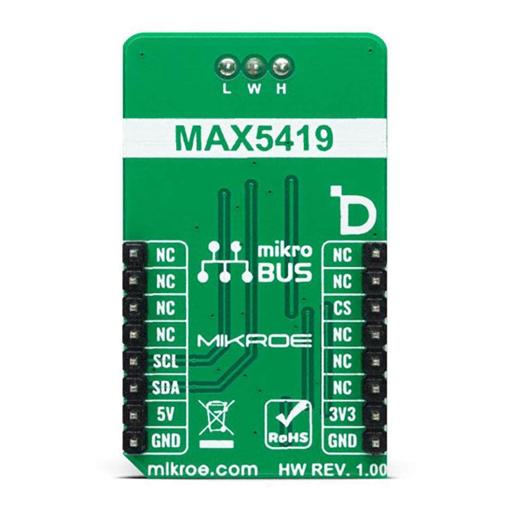
- Basierend auf dem MAX5419 - digitales Potentiometer von Analog Devices
- Kann für die Entwicklung von mechanischen Potentiometer-Ersatzteilen für den tragbaren Verbrauchermarkt, für Lautstärkeregler, LCD-Kontrastregler und industrielle Anwendungen mit Batterie-Backup verwendet werden
- mikroBUS: I2C-Schnittstelle
Einführung des DIGI POT 13 Click Board™
Das DIGI POT 13 Click Board™ ist Ihre kompakte Lösung für präzise Steuerung. Mit seinem digital gesteuerten Potentiometer revolutioniert diese Zusatzplatine Ihre elektronischen Projekte. Verabschieden Sie sich von herkömmlichen mechanischen Potentiometern und nutzen Sie den Komfort und die Flexibilität des DIGI POT 13 Click Board™.
Erweiterte Funktionen
Spitzentechnologie
Das Herzstück des DIGI POT 13 Click Board™ ist der MAX5419, ein hochmodernes nichtflüchtiges digitales Potentiometer mit 256 Abgriffen von Analog Devices. Erleben Sie mit diesem bemerkenswerten Board den Höhepunkt der digitalen Potentiometertechnologie.
Einstellbarer Widerstand
Mit einem typischen End-zu-End-Widerstandswert von 200 kΩ ermöglicht Ihnen das DIGI POT 13 Click Board™ eine präzise Feinabstimmung Ihrer Schaltkreise. Erreichen Sie mühelos den gewünschten Widerstand und optimieren Sie Ihre elektronischen Designs.
Vielseitige Energieoptionen
Das DIGI POT 13 Click Board™ wurde für Ihre Anforderungen entwickelt und kann problemlos mit 3,3-V- und 5-V-Stromversorgungen betrieben werden. Genießen Sie die Flexibilität bei der Auswahl der Stromquelle, die Ihren Projektanforderungen entspricht.
Temperaturstabilität
Erleben Sie außergewöhnliche Leistung selbst bei schwankenden Temperaturen. Das DIGI POT 13 Click Board™ bietet einen niedrigen End-to-End-Nennwiderstandstemperaturkoeffizienten von 35 ppm/ºC und einen beeindruckenden ratiometrischen Wert von 5 ppm/ºC. Halten Sie Ihre Schaltkreise stabil und zuverlässig.
Anwendungen
Das DIGI POT 13 Click Board™ ist die ultimative Lösung für eine Vielzahl von Anwendungen. Ganz gleich, ob Sie Produkte für den tragbaren Verbrauchermarkt entwickeln, an Lautstärkeregelungssystemen arbeiten, den LCD-Kontrast anpassen oder batteriegestützte Industrieanwendungen entwickeln, dieses Click Board™ ist für Sie da.
Vereinfachte Softwareentwicklung
Unterstützt durch eine mikroSDK-kompatible Bibliothek macht das DIGI POT 13 Click Board™ die Softwareentwicklung zum Kinderspiel. Nutzen Sie die enthaltenen Funktionen, die Ihren Codierungsprozess optimieren. Verabschieden Sie sich von unnötiger Komplexität und begrüßen Sie die Effizienz.
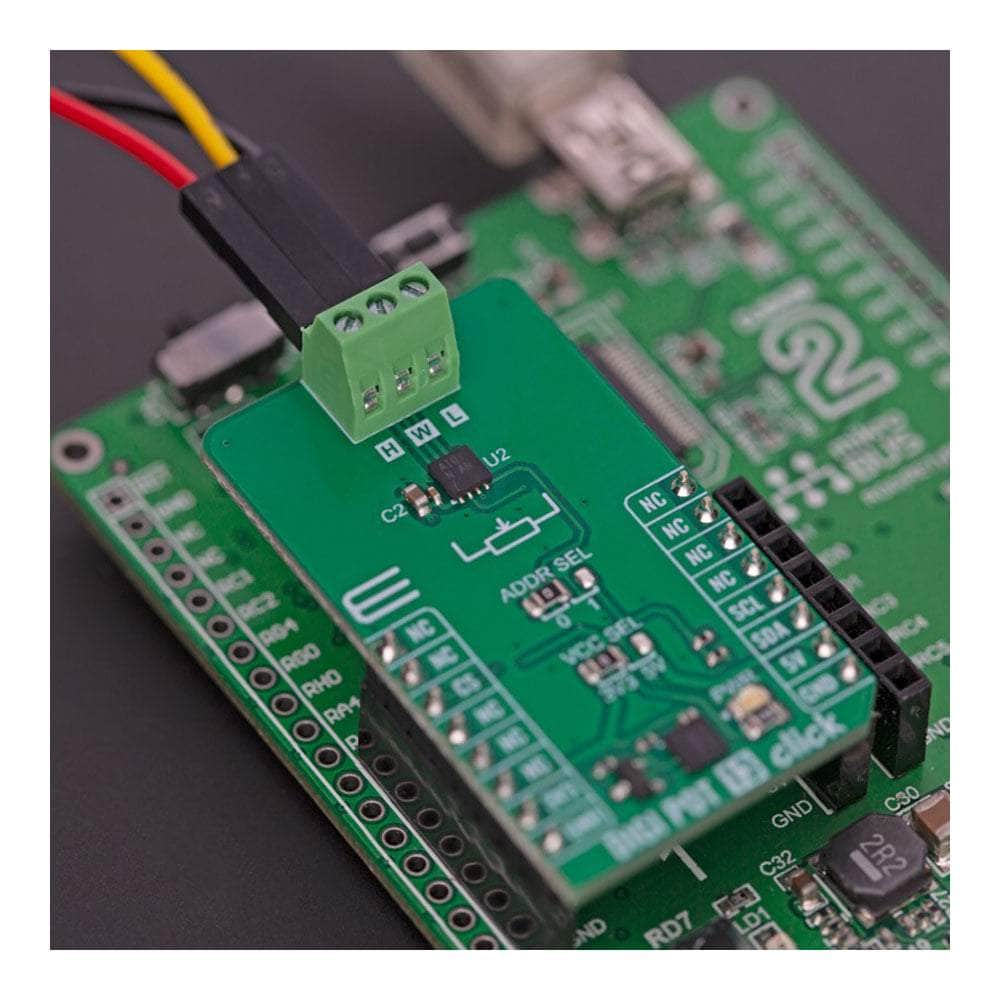
Sofort einsatzbereit
Das DIGI POT 13 Click Board™ wird vollständig getestet geliefert und ist bereit zur Integration in Ihre Projekte. Dank der MikroBUS™-Sockelkompatibilität können Sie dieses Click Board™ problemlos in jedes System integrieren, das es unterstützt. Beginnen Sie noch heute Ihre Reise zu verbesserter Kontrolle und Präzision mit dem DIGI POT 13 Click Board™.
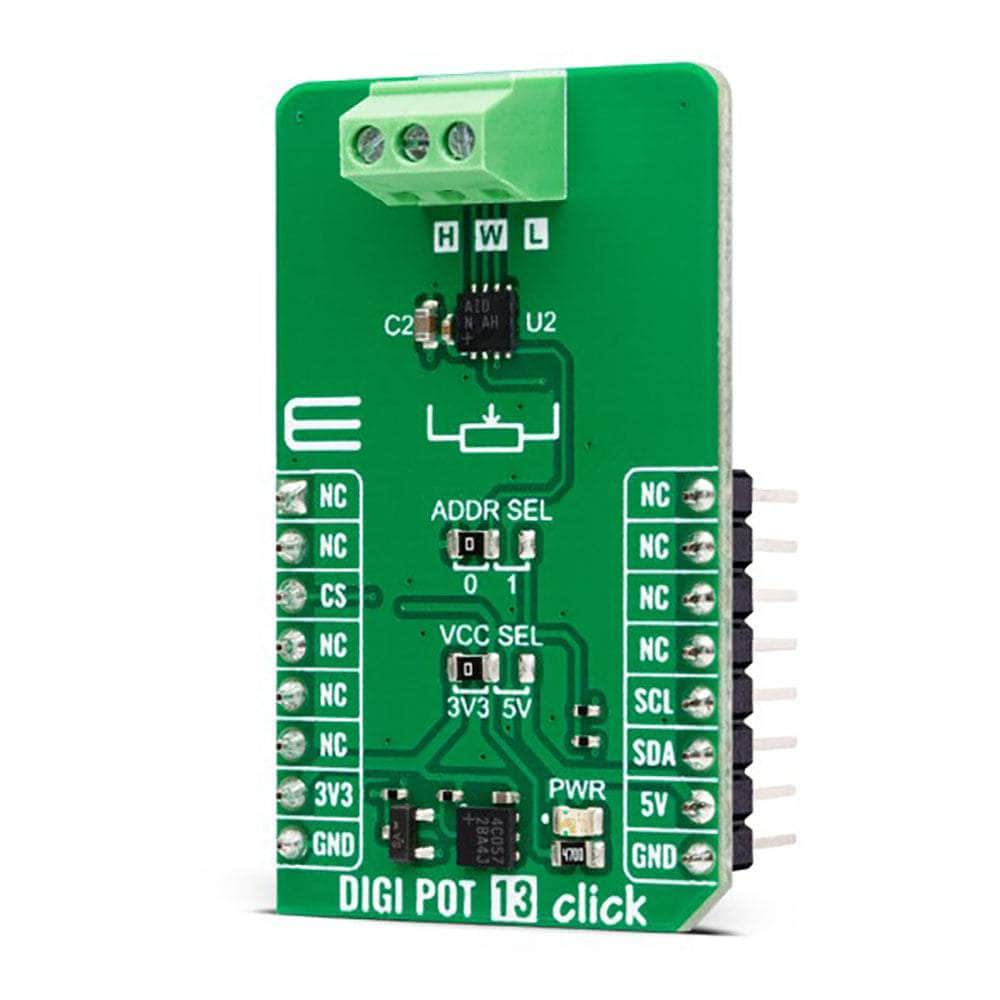

How Does The DIGI POT 13 Click Board™ Work?
The DIGI POT 13 Click Board™ is based on the MAX5419, a 256-tap non-volatile digital potentiometer from Analog Devices. It can perform as a discrete potentiometer or variable resistor. The potentiometers consist of a resistor array with 255 fixed resistor elements in series between appropriate H and L terminals. The potentiometer wiper (W) terminal is programmable to access any one of the 256 tap points on the resistor string, with typically 325 ohms of wiper resistance and 150-250kΩ of end-to-end resistance (200kΩ typical). It also features a power-on reset circuitry that loads the wiper position from non-volatile memory at power up. The memory is guaranteed for 50 years for wiper data retention and up to 200.000 wiper store cycles.
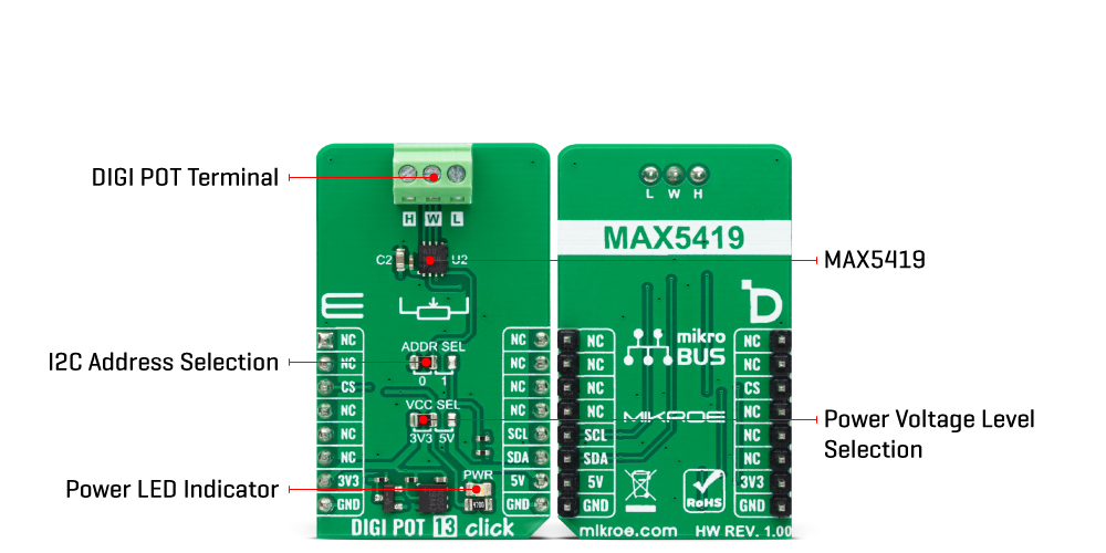
The DIGI POT 13 Click Board™ communicates with the host MCU using the standard I2C 2-Wire interface, with a maximum clock frequency in Fast data transfer of up to 400KHz (400kbps). The I2C address can be selected via the ADDR SEL jumper with 0 selected by default. Over the I2C interface, all data can be stored in an internal 8-bit EEPROM.
This Click board™ can operate with either 3.3V or 5V logic voltage levels selected via the VCC SEL jumper. This way, both 3.3V and 5V capable MCUs can use the communication lines properly. However, the Click board™ comes equipped with a library containing easy-to-use functions and an example code that can be used, as a reference, for further development.
SPECIFICATIONS
| Type | Digital potentiometer |
| Applications | It can be used for the development of mechanical potentiometer replacements for the portable consumer market, volume control, LCD contrast control, and battery-backup industrial applications |
| On-board modules | MAX5419 - digital potentiometer from Analog Devices |
| Key Features | Single channel, single supply operation, 256-position resolution, 200kΩ nominal resistance, I2C-compatible interface, nonvolatile memory stores wiper settings, 50 years of typical data retention, and more |
| Interface | I2C |
| Compatibility | mikroBUS |
| Click board size | M (42.9 x 25.4 mm) |
| Input Voltage | 3.3V or 5V |
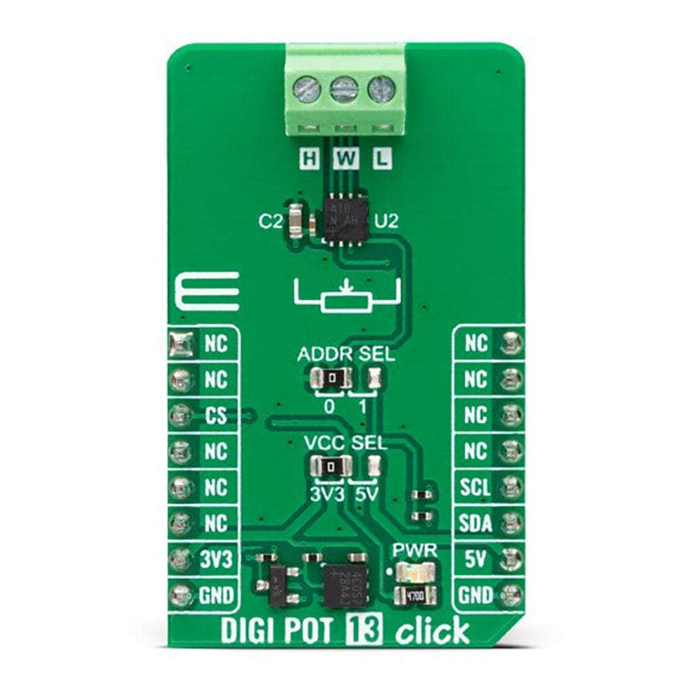
PINOUT DIAGRAM
This table shows how the DIGI POT 13 Click Board™ pinout corresponds to the pinout on the mikroBUS™ socket (the latter shown in the two middle columns).
| Notes | Pin | Pin | Notes | ||||
|---|---|---|---|---|---|---|---|
| NC | 1 | AN | PWM | 16 | NC | ||
| NC | 2 | RST | INT | 15 | NC | ||
| NC | 3 | CS | RX | 14 | NC | ||
| NC | 4 | SCK | TX | 13 | NC | ||
| NC | 5 | MISO | SCL | 12 | SCL | I2C Clock | |
| NC | 6 | MOSI | SDA | 11 | SDA | I2C Data | |
| Power Supply | 3.3V | 7 | 3.3V | 5V | 10 | 5V | Power Supply |
| Ground | GND | 8 | GND | GND | 9 | GND | Ground |
ONBOARD SETTINGS AND INDICATORS
| Label | Name | Default | Description |
|---|---|---|---|
| LD1 | PWR | - | Power LED Indicator |
| JP1 | VCC SEL | Left | Logic Level Voltage Selection 3V3/5V: Left position 3V3, Right position 5V |
| JP2 | ADDR SEL | Left | I2C Address Selection 0/1: Left position 0, Right position 1 |
DIGI POT 13 CLICK ELECTRICAL SPECIFICATIONS
| Description | Min | Typ | Max | Unit |
|---|---|---|---|---|
| Supply Voltage | 3.3 | - | 5 | V |
| Nominal Resistance | - | 200 | - | kΩ |
| Resolution | - | 256 | - | taps |
| Wiper Resistance | - | 325 | - | Ω |
Software Support
Software Support
We provide a library for the DIGI POT 13 Click Board™ as well as a demo application (example), developed using MIKROE compilers. The demo can run on all the main MIKROE development boards.
The package can be downloaded/installed directly from NECTO Studio The package Manager (recommended), downloaded from our LibStock™ or found on MikroE Github account.
Library Description
This library contains API for the DIGI POT 13 Click Board™ driver.
Key functions
-
digipot13_set_resistanceDIGI POT 13 set the resistance function. -
digipot13_set_wiper_posDIGI POT 13 set the wiper position function. -
digipot13_write_dataDIGI POT 13 write data function.
Example Description
This library contains API for the DIGI POT 13 Click Board™ driver. The demo application uses a digital potentiometer to change the resistance values.
void application_task ( void )
 {
     for ( uint8_t res_kohm = DIGIPOT13_RES_0_KOHM; res_kohm <= DIGIPOT13_RES_200_KOHM; res_kohm += DIGIPOT13_RES_50_KOHM )
     {
         if ( DIGIPOT13_OK == digipot13_set_resistance( &digipot13, DIGIPOT13_CFG_RES_WH, ( float ) res_kohm ) )
         {
             log_printf( &logger, " Resistance: %.1f kOhmrn", ( float ) res_kohm );
             log_printf( &logger, " ----------------------------rn" );
             Delay_ms( 5000 );
         }
     }
 }
The full application code, and ready to use projects can be installed directly from NECTO Studio The package Manager (recommended), downloaded from our LibStock™ or found on MikroE Github account.
Other MikroE Libraries used in the example:
- MikroSDK.Board
- MikroSDK.Log
- Click.DIGIPOT13
Additional Notes and Information
This Click board™ is supported with mikroSDK - MIKROE Software Development Kit, that needs to be downloaded from the LibStock and installed for the compiler you are using to ensure proper operation of mikroSDK compliant Click board™ demo applications.
MIKROSDK
The DIGI POT 13 Click Board™ is supported with mikroSDK - MIKROE Software Development Kit, that needs to be downloaded from the LibStock and installed for the compiler you are using to ensure proper operation of mikroSDK compliant Click board™ demo applications.
DIGI POT 13 Click-Platine
Frequently Asked Questions
Have a Question?
Be the first to ask a question about this.