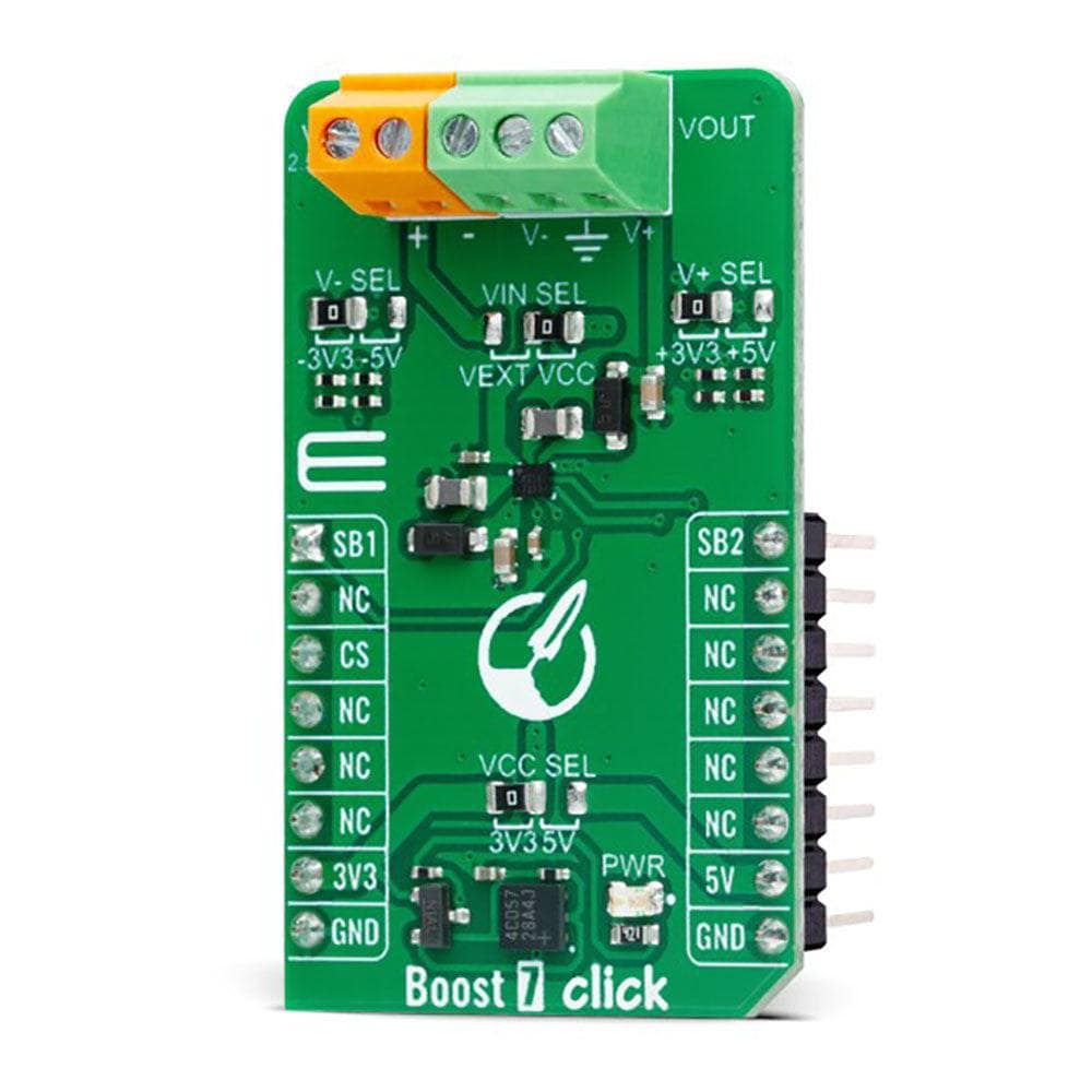
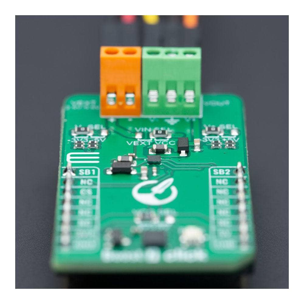
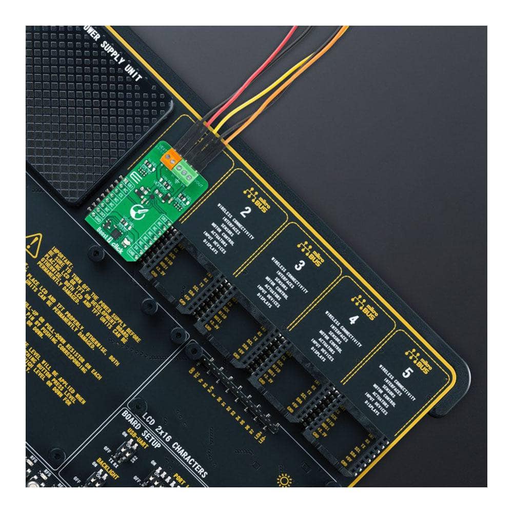
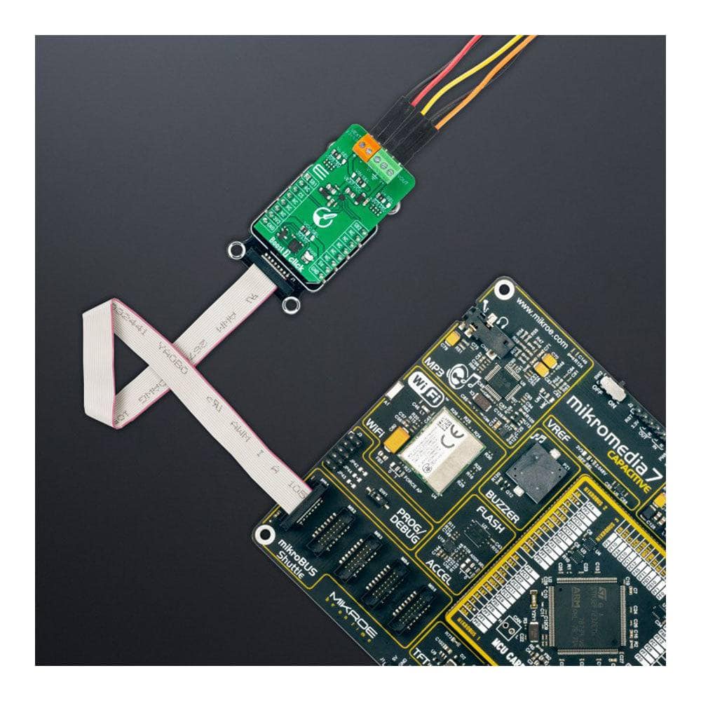
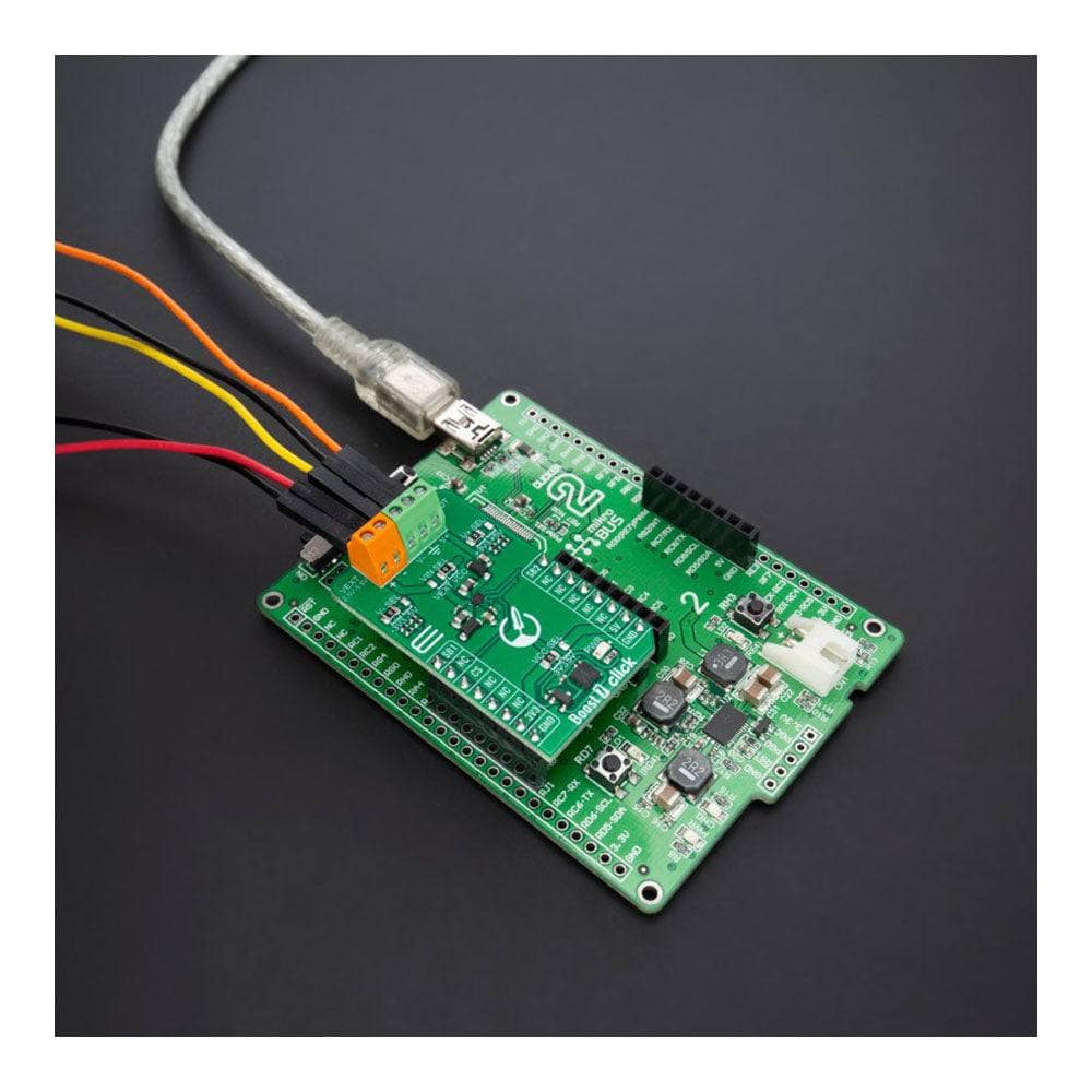
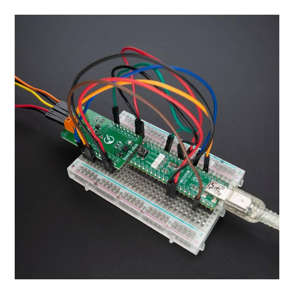
Boost 7 Klicken Sie auf Board
Key Features
- Geregelte negative und positive Ausgänge, strombegrenzt, hohe Effizienz, geringer Stromverbrauch, wählbare Konverterstromversorgung, digital gesteuerte Ausgangskanäle und mehr
- Basierend auf dem BD8316GWL - dualer DC/DC-Wandler von Rohm Semiconductor
- Kann verwendet werden, um eine Eingangsspannung auf ein höheres Niveau zu erhöhen
- mikroBUS: GPIO-Schnittstelle
Steigern Sie Ihre Spannung mit dem Boost 7 Click Board™
Möchten Sie die Spannung für Ihre Last erhöhen? Dann sind Sie mit dem Boost 7 Click Board™ genau richtig. Das kompakte Zusatzboard bietet zuverlässige Spannungsregelung für zahlreiche Anwendungen.
Starke Leistung, minimaler Platzbedarf
Das Boost 7 Click Board™ ist mit dem fortschrittlichen dualen DC/DC-Wandler BD8316GWL von Rohm Semiconductor ausgestattet und bietet eine Strombegrenzung von bis zu 200 mA sowie gut geregelte positive und negative Ausgänge von ±3,3 V oder ±5 V. Dadurch eignet es sich ideal für eine Vielzahl von Anwendungen, die Split-Rail-Betriebsspannungen erfordern.
Vielseitige Kompatibilität
Das Boost 7 Click Board™ ist mit beiden mikroBUS™-Stromschienen kompatibel und unterstützt auch eine externe Stromversorgung mit einer sehr niedrigen Spannung von 2,5 V. Dies gibt Ihnen die Flexibilität, die Sie brauchen, um Ihre Last mit Strom zu versorgen, egal wo Sie sind.
Vereinfachte Softwareentwicklung
Mit der mikroSDK-kompatiblen Bibliothek war die Softwareentwicklung für das Boost 7 Click Board™ noch nie so einfach. Unsere Bibliothek enthält Funktionen, die die Softwareentwicklung vereinfachen, sodass Sie schnell und einfach loslegen können.
Sofort einsatzbereit
Das Boost 7 Click Board™ wird vollständig getestet und ist einsatzbereit auf jedem System, das mit der mikroBUS™-Buchse ausgestattet ist. Worauf also warten? Steigern Sie Ihre Spannung und bringen Sie Ihre Anwendungen noch heute mit dem Boost 7 Click Board™ auf Touren!How Does The Boost 7 Click Board™ Work?
The Boost 7 Click Board™ is based on the LT1945, a dual step-up and inverted DC/DC converter from Rohm Semiconductor that boosts an input voltage to a higher level required by an output load. The BD8316GWL switching regulator feature integrated N-channel FETs and power P-channel MOSFETs alongside a Soft Start feature. Each converter inside the LT1945 is designed with up to 200mA current limit generating well-regulated positive and negative outputs of ±3.3V or ±5V, making the BD8316GWL ideal for various portable applications.
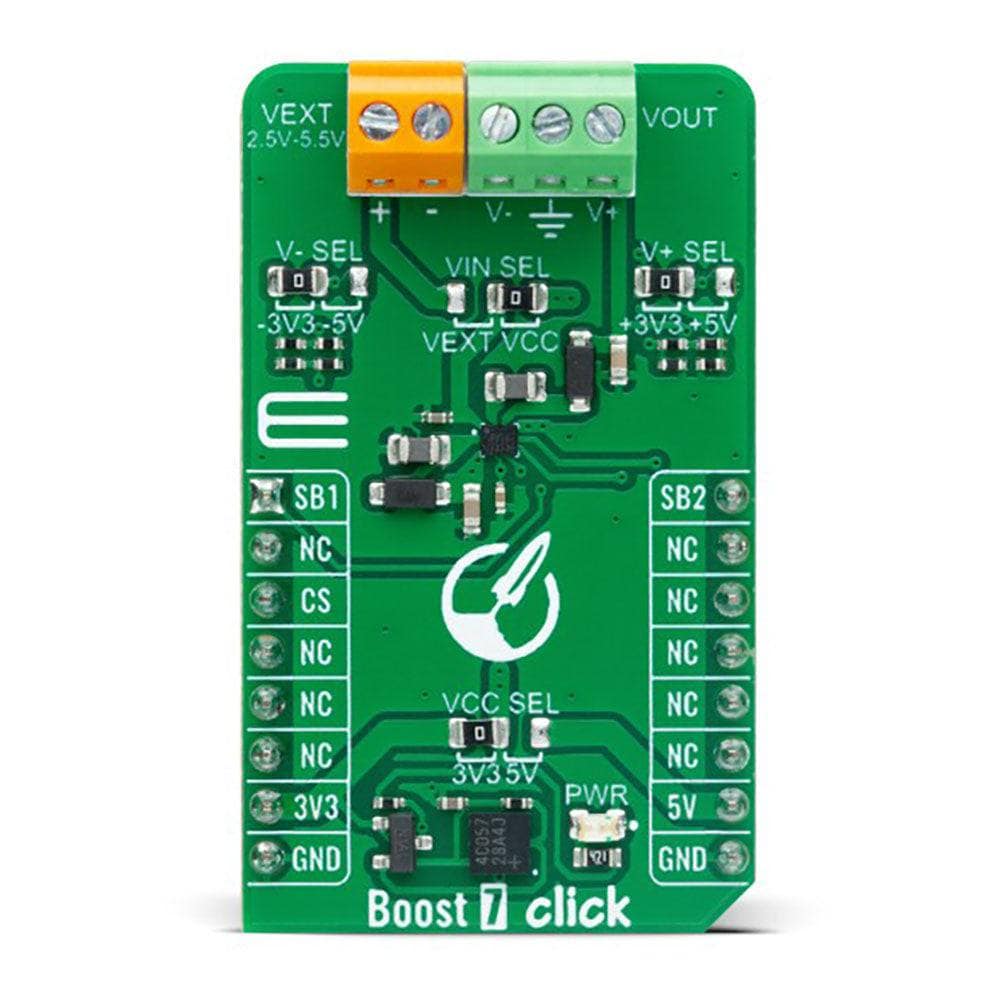
As mentioned, the BD8316GWL can configure the positive and negative output voltage in the ±3.3V or ±5V range. The desired output voltage can be selected by positioning SMD jumpers labelled as V- SEL and V+ SEL to an appropriate position. It is also possible to control the activity of the output channels via two mikroBUS™ pins, SB1 and SB2 pins. These pins are routed to a default position of the AN and PWM pins of the mikroBUS™ socket. By setting these pins to a high logic state, we put the converter outputs to an active state, and regulated voltages are available at the output terminals. In the same way, setting these pins to a low logic level disables the channels.
The Boost 7 Click Board™ can operate with either 3.3V or 5V logic voltage levels selected via the VCC SEL jumper. This way, both 3.3V and 5V capable MCUs can use the communication lines properly. Additionally, there is a possibility for the BD8316GWL power supply selection via jumper labelled as VIN SEL to supply the BD8316GWL from an external power supply terminal in the range from 2.5V to 5.5V or with a selected voltage from mikroBUS™ power rails. However, the Click board™ comes equipped with a library containing easy-to-use functions and an example code that can be used, as a reference, for further development.
SPECIFICATIONS
Type | Boost |
Applications | Can be used to step up an input voltage to some higher level |
On-board modules | BD8316GWL - dual DC/DC converter from Rohm Semiconductor |
Key Features | Regulated negative and positive outputs, current-limited, high efficiency, low power consumption, selectable converter power supply, digitally-controlled output channels, and more |
Interface | GPIO |
Compatibility | mikroBUS |
Click board size | M (42.9 x 25.4 mm) |
Input Voltage | 3.3V or 5V,External |
PINOUT DIAGRAM
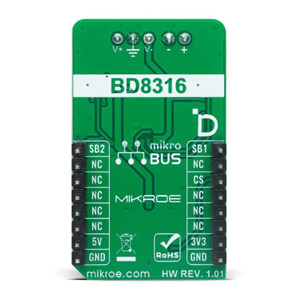
This table shows how the pinout of the Boost 7 Click Board™ corresponds to the pinout on the mikroBUS™ socket (the latter shown in the two middle columns).
Notes | Pin | Pin | Notes | ||||
---|---|---|---|---|---|---|---|
Negative Channel Control | SB1 | 1 | AN | PWM | 16 | SB2 | Positive Channel Control |
NC | 2 | RST | INT | 15 | NC | ||
NC | 3 | CS | RX | 14 | NC | ||
NC | 4 | SCK | TX | 13 | NC | ||
NC | 5 | MISO | SCL | 12 | NC | ||
NC | 6 | MOSI | SDA | 11 | NC | ||
Power Supply | 3.3V | 7 | 3.3V | 5V | 10 | 5V | Power Supply |
Ground | GND | 8 | GND | GND | 9 | GND | Ground |
ONBOARD SETTINGS AND INDICATORS
Label | Name | Default | Description |
---|---|---|---|
LD1 | PWR | - | Power LED Indicator |
JP1 | V-SEL | Left | Negative Output Voltage Selection -3.3V/-5V: Left position -3.3V, Right position -5V |
JP2 | V+SEL | Left | Positive Output Voltage Selection +3.3V/+5V: Left position +3.3V, Right position +5V |
JP3 | VCC SEL | Left | Logic Level Voltage Selection 3V3/5V: Left position 3V3, Right position 5V |
JP4 | VIN SEL | Right | BD8316GWL Power Supply Selection VEXT/VCC: Left position VEXT, Right position VCC |
BOOST 7 CLICK ELECTRICAL SPECIFICATIONS
Description | Min | Typ | Max | Unit |
---|---|---|---|---|
Supply Voltage | 3.3 | - | 5 | V |
External Supply Voltage | 2.5 | - | 5.5 | V |
Positive Output Voltage | - | +3.3/+5 | - | V |
Negative Output Voltage | - | -3.3/-5 | - | V |
Software Support
Software Support
We provide a library for the Boost 7 Click Board™ as well as a demo application (example), developed using MikroE compilers. The demo can run on all the main MikroE development boards.
The package can be downloaded/installed directly from NECTO Studio The package Manager (recommended), downloaded from our LibStock™ or found on MikroE Github account.
Library Description
This library contains API for the Boost 7 Click Board™ driver.
Key functions
-
boost7_enable_out1
This function enables the OUT1 (V-) by setting the STB1 pin to high logic state. -
boost7_disable_out1
This function disables the OUT1 (V-) by setting the STB1 pin to low logic state. -
boost7_enable_out2
This function enables the OUT2 (V+) by setting the STB2 pin to high logic state.
Example Description
This example demonstrates the use of the Boost 7 Click Board™ by controlling the V- and V+ outputs state.
void application_task ( void )
{
log_printf( &logger, " OUT1 (V-) : ENABLEDrn" );
log_printf( &logger, " OUT2 (V+) : DISABLEDrnn" );
boost7_enable_out1 ( &boost7 );
boost7_disable_out2 ( &boost7 );
Delay_ms( 5000 );
log_printf( &logger, " OUT1 (V-) : DISABLEDrn" );
log_printf( &logger, " OUT2 (V+) : ENABLEDrnn" );
boost7_disable_out1 ( &boost7 );
boost7_enable_out2 ( &boost7 );
Delay_ms( 5000 );
}
The full application code, and ready to use projects can be installed directly from NECTO Studio The package Manager (recommended), downloaded from our LibStock™ or found on MikroE Github account.
Other MikroE Libraries used in the example:
- MikroSDK.Board
- MikroSDK.Log
- Click.Boost7
Additional Notes and Information
Depending on the development board you are using, you may need USB UART Click Board™, USB UART 2 Click or RS232 Click to connect to your PC, for development systems with no UART to USB interface available on the board. A UART terminal is available in all MikroE compilers.
MIKROSDK
The Boost 7 Click Board™ is supported with mikroSDK - MikroE Software Development Kit. To ensure proper operation of mikroSDK compliant Click board™ demo applications, mikroSDK should be downloaded from the LibStock and installed for the compiler you are using.
Software Support
Software Support
We provide a library for the Boost 7 Click Board™ as well as a demo application (example), developed using MikroE compilers. The demo can run on all the main MikroE development boards.
The package can be downloaded/installed directly from NECTO Studio The package Manager (recommended), downloaded from our LibStock™ or found on MikroE Github account.
Library Description
This library contains API for the Boost 7 Click Board™ driver.
Key functions
-
boost7_enable_out1
This function enables the OUT1 (V-) by setting the STB1 pin to high logic state. -
boost7_disable_out1
This function disables the OUT1 (V-) by setting the STB1 pin to low logic state. -
boost7_enable_out2
This function enables the OUT2 (V+) by setting the STB2 pin to high logic state.
Example Description
This example demonstrates the use of the Boost 7 Click Board™ by controlling the V- and V+ outputs state.
void application_task ( void )
{
log_printf( &logger, " OUT1 (V-) : ENABLEDrn" );
log_printf( &logger, " OUT2 (V+) : DISABLEDrnn" );
boost7_enable_out1 ( &boost7 );
boost7_disable_out2 ( &boost7 );
Delay_ms( 5000 );
log_printf( &logger, " OUT1 (V-) : DISABLEDrn" );
log_printf( &logger, " OUT2 (V+) : ENABLEDrnn" );
boost7_disable_out1 ( &boost7 );
boost7_enable_out2 ( &boost7 );
Delay_ms( 5000 );
}
The full application code, and ready to use projects can be installed directly from NECTO Studio The package Manager (recommended), downloaded from our LibStock™ or found on MikroE Github account.
Other MikroE Libraries used in the example:
- MikroSDK.Board
- MikroSDK.Log
- Click.Boost7
Additional Notes and Information
Depending on the development board you are using, you may need USB UART Click Board™, USB UART 2 Click or RS232 Click to connect to your PC, for development systems with no UART to USB interface available on the board. A UART terminal is available in all MikroE compilers.
MIKROSDK
The Boost 7 Click Board™ is supported with mikroSDK - MikroE Software Development Kit. To ensure proper operation of mikroSDK compliant Click board™ demo applications, mikroSDK should be downloaded from the LibStock and installed for the compiler you are using.
Boost 7 Klicken Sie auf Board
Frequently Asked Questions
Ask a Question-
Is the Boost 7 Click Board™ ready to use?
Yes, the Boost 7 Click Board™ comes as a fully tested product, ready to be used on a system equipped with the mikroBUS™ socket.
-
What is the mikroSDK-compliant library for the Boost 7 Click Board™?
The Boost 7 Click Board™ is supported by a mikroSDK-compliant library, which includes functions that simplify software development.
-
What are the applications of the Boost 7 Click Board™?
The Boost 7 Click Board™ is used to step up an input voltage to some higher level required by a load, for various applications that require "split rail" operating voltages.
-
What is the voltage range of the external power supply that can be used with the Boost 7 Click Board™?
The Boost 7 Click Board™ provides the opportunity of using an external power supply with a very low voltage of 2.5V.
-
What is the current limit of each converter inside the BD8316GWL?
Each converter inside the BD8316GWL is designed with up to 200mA current limit.
-
What is the Boost 7 Click Board™?
The Boost 7 Click Board™ is an add-on board that steps up the voltage from its input (supply) to its output (load). It features the BD8316GWL, a dual DC/DC converter from Rohm Semiconductor, which is designed to generate well-regulated positive and negative outputs of ±3.3V or ±5V.