

Mikroelektronika d.o.o.
LED-Treiber 17 Click-Platine
LED-Treiber 17 Click-Platine
SKU: MIKROE-5565
Verfügbarkeit für Abholungen konnte nicht geladen werden


Key Features
Overview
Introducing the LED Driver 17 Click Board™ - The Ultimate Solution for LED Control
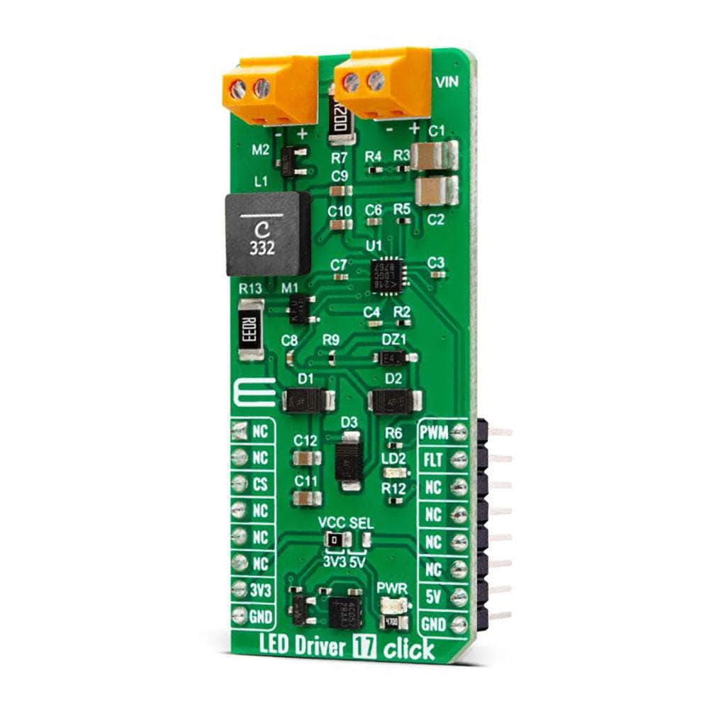
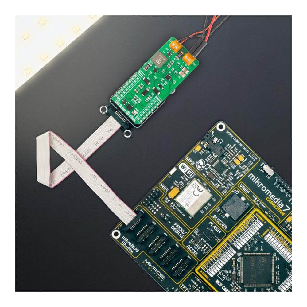
Discover the LED Driver 17 Click Board™, a compact and versatile add-on board that offers a simple yet powerful solution for controlling multiple LEDs in various applications. Whether you're working on architectural lighting, general lighting, or just exploring your creativity with LEDs, this is the perfect choice for you!
Featuring the LTR3755 - A High-Efficiency DC/DC Controller from Analog Devices
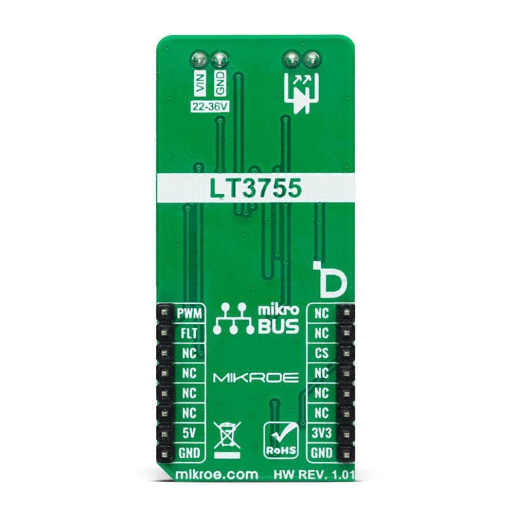
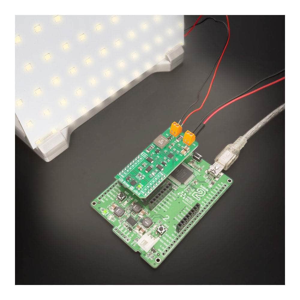
At the heart of this remarkable board is the LTR3755, a highly efficient DC/DC controller designed to operate as a constant-current source. With the ability to easily drive high-current LEDs and onboard low-side external N-channel power MOSFETs, the LED Driver 17 Click Board™ ensures stable operation over a wide supply range.
Comprehensive LED Protection Features
Designed with user safety in mind, the LED Driver 17 Click Board™ offers several essential protection features for your LEDs, including overvoltage and overcurrent protection. Plus, the frequency adjust pin allows you to program the switching frequency from 100kHz to 1MHz, optimizing efficiency and performance to suit your needs.
Supported by mikroSDK - Simplifying Software Development
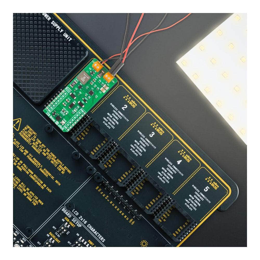
When it comes to software development, the LED Driver 17 Click Board™ has you covered. It is supported by a mikroSDK-compliant library, which includes functions that make software development a breeze. This Click board™ comes as a fully tested product, ready to be integrated into any system equipped with the mikroBUS™ socket.
A Versatile Choice for Hobbyists and Professionals Alike
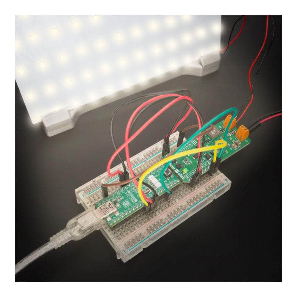
Whether you're a hobbyist or a professional, the LED Driver 17 Click Board™ is the ideal choice for controlling multiple LEDs in various settings. With its comprehensive features, ease of use, and reliable performance, this Click board™ will undoubtedly enhance your LED projects and applications.
Downloads
Einführung des LED-Treibers 17 Click Board™ – die ultimative Lösung zur LED-Steuerung
Entdecken Sie das LED Driver 17 Click Board™, eine kompakte und vielseitige Zusatzplatine, die eine einfache und dennoch leistungsstarke Lösung zur Steuerung mehrerer LEDs in verschiedenen Anwendungen bietet. Egal, ob Sie an Architekturbeleuchtung oder Allgemeinbeleuchtung arbeiten oder einfach nur Ihre Kreativität mit LEDs ausleben, dies ist die perfekte Wahl für Sie!
Mit dem LTR3755 – einem hocheffizienten DC/DC-Controller von Analog Devices
Das Herzstück dieser bemerkenswerten Platine ist der LTR3755, ein hocheffizienter DC/DC-Controller, der als Konstantstromquelle fungiert. Mit der Fähigkeit, Hochstrom-LEDs und integrierte externe Low-Side-N-Kanal-Leistungs-MOSFETs problemlos anzusteuern, gewährleistet das LED Driver 17 Click Board™ einen stabilen Betrieb über einen weiten Versorgungsspannungsbereich.
Umfassende LED-Schutzfunktionen
Das LED Driver 17 Click Board™ wurde mit Blick auf die Benutzersicherheit entwickelt und bietet mehrere wichtige Schutzfunktionen für Ihre LEDs, einschließlich Überspannungs- und Überstromschutz. Darüber hinaus können Sie mit dem Frequenzanpassungsstift die Schaltfrequenz von 100 kHz bis 1 MHz programmieren und so Effizienz und Leistung entsprechend Ihren Anforderungen optimieren.
Unterstützt durch mikroSDK – Vereinfachung der Softwareentwicklung
Wenn es um Softwareentwicklung geht, sind Sie mit dem LED Driver 17 Click Board™ bestens bedient. Es wird von einer mikroSDK-kompatiblen Bibliothek unterstützt, die Funktionen enthält, die die Softwareentwicklung zum Kinderspiel machen. Dieses Click Board™ ist ein vollständig getestetes Produkt und kann in jedes System integriert werden, das mit der mikroBUS™-Buchse ausgestattet ist.
Eine vielseitige Wahl für Hobbyisten und Profis
Egal, ob Sie Hobbyist oder Profi sind, das LED Driver 17 Click Board™ ist die ideale Wahl für die Steuerung mehrerer LEDs in verschiedenen Einstellungen. Mit seinen umfassenden Funktionen, seiner Benutzerfreundlichkeit und seiner zuverlässigen Leistung wird dieses Click Board™ Ihre LED-Projekte und -Anwendungen zweifellos verbessern.
| General Information | |
|---|---|
Part Number (SKU) |
MIKROE-5565
|
Manufacturer |
|
| Physical and Mechanical | |
Weight |
0.02 kg
|
| Other | |
EAN |
8606027384936
|
Frequently Asked Questions
Have a Question?
Be the first to ask a question about this.