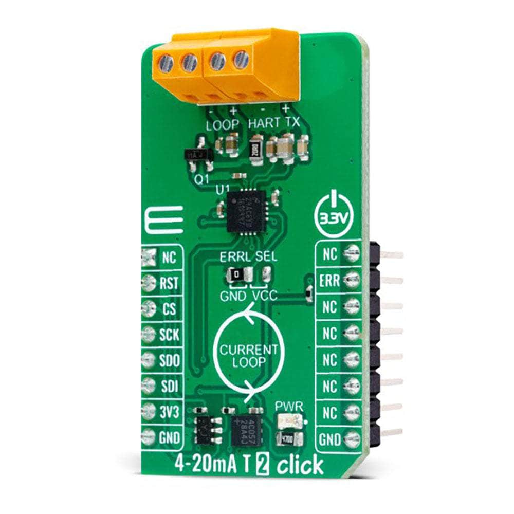
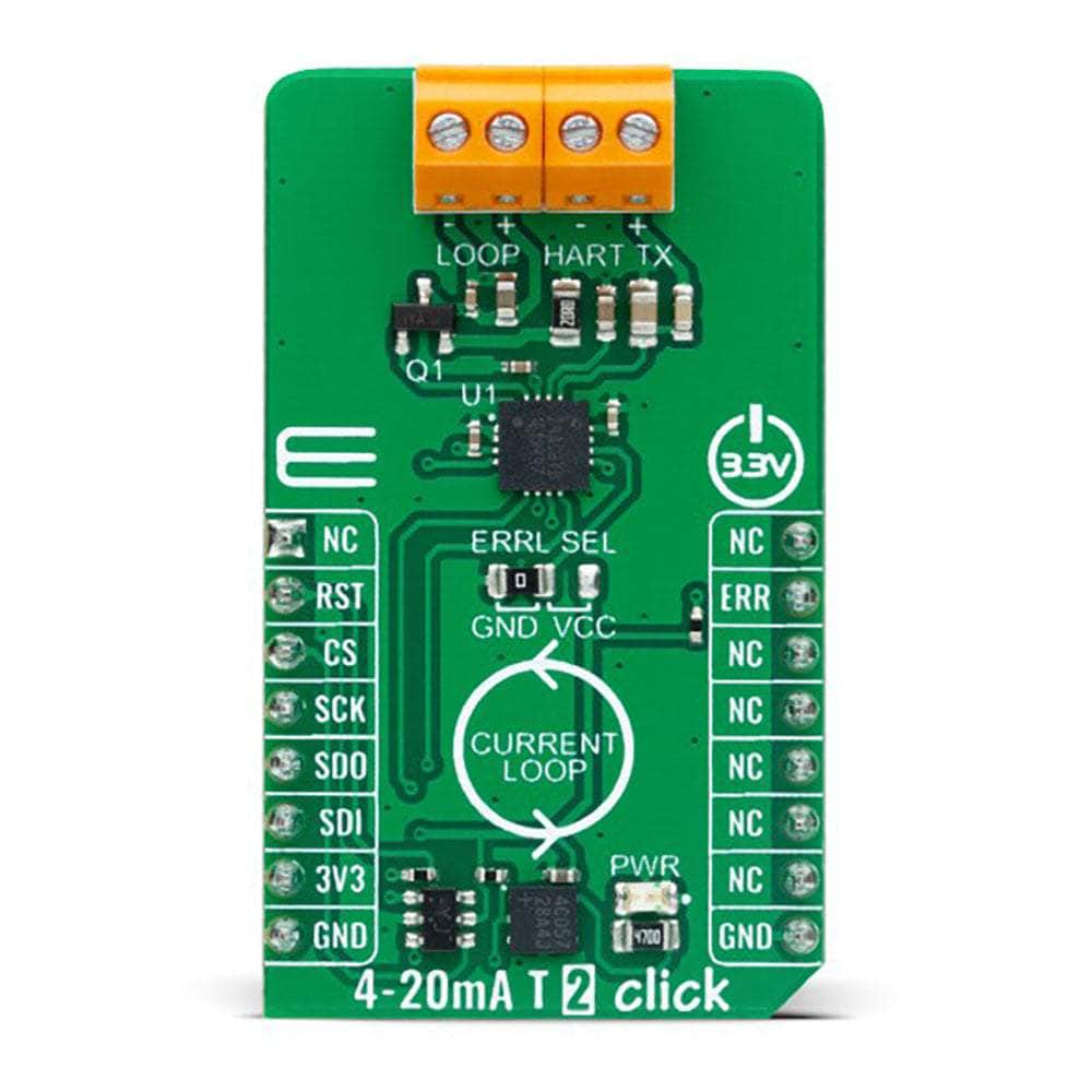
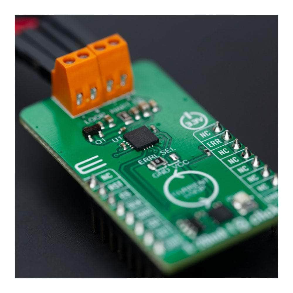
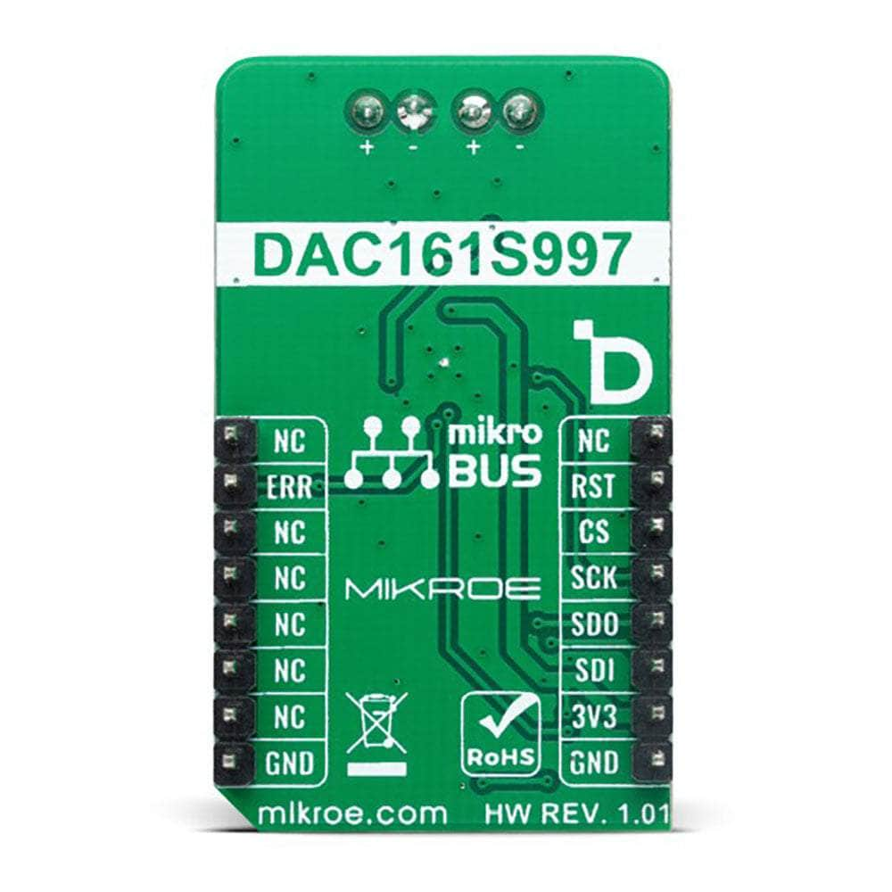
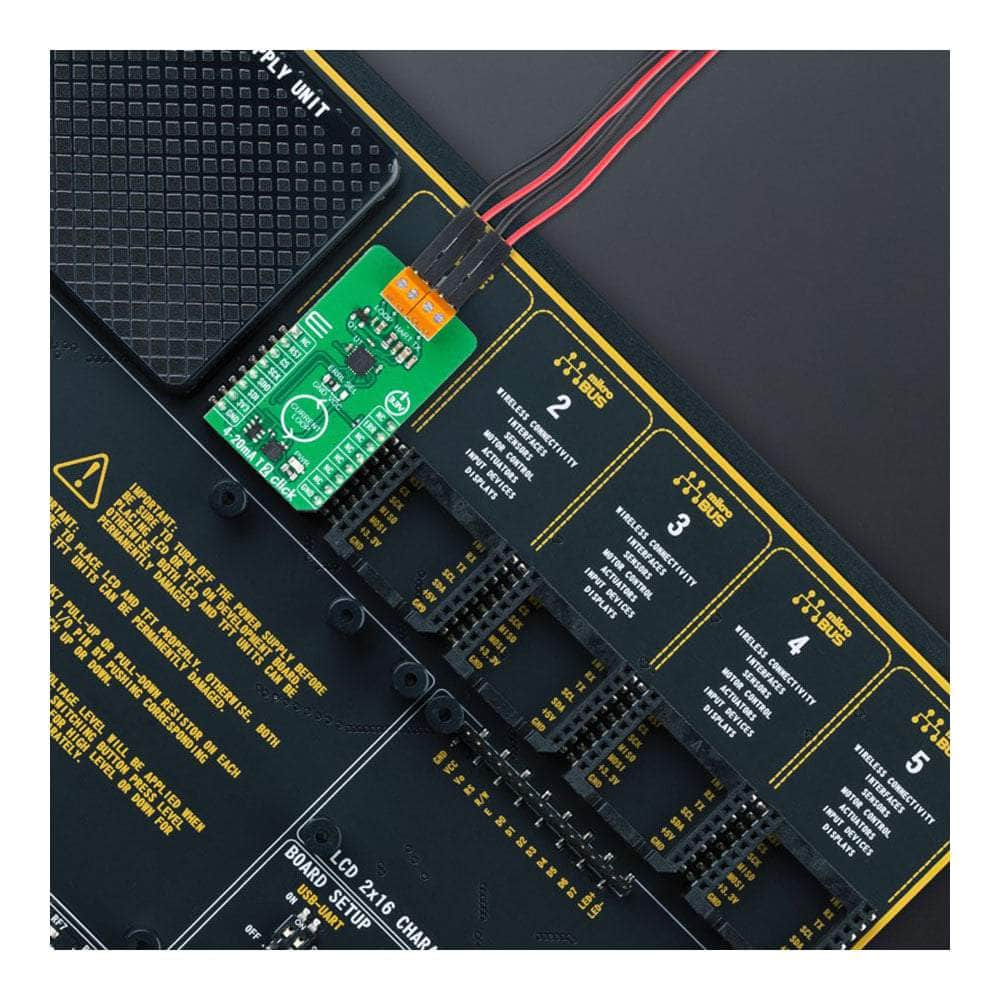
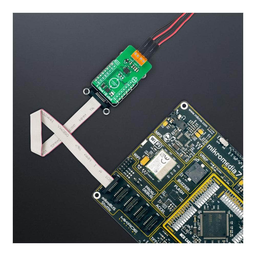
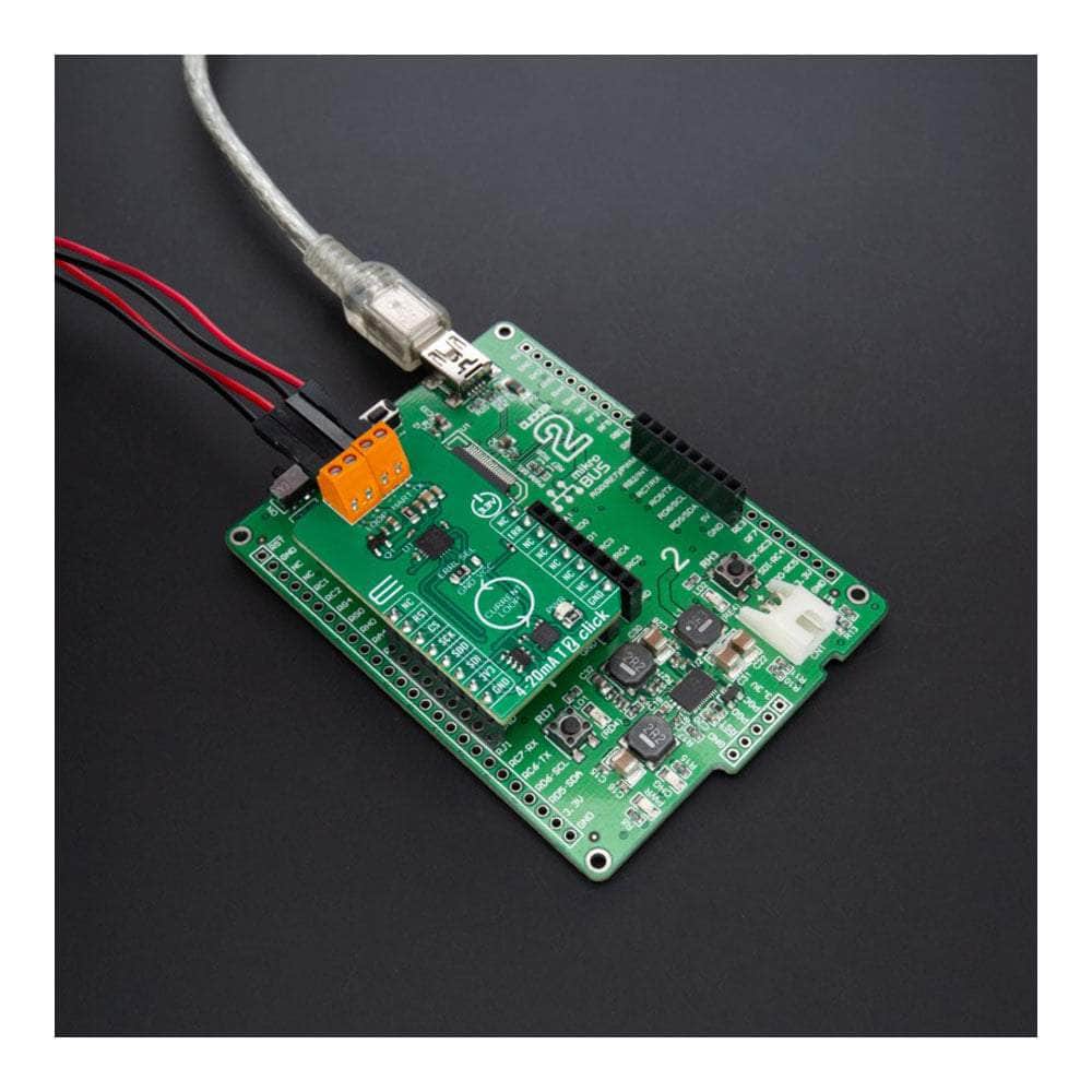
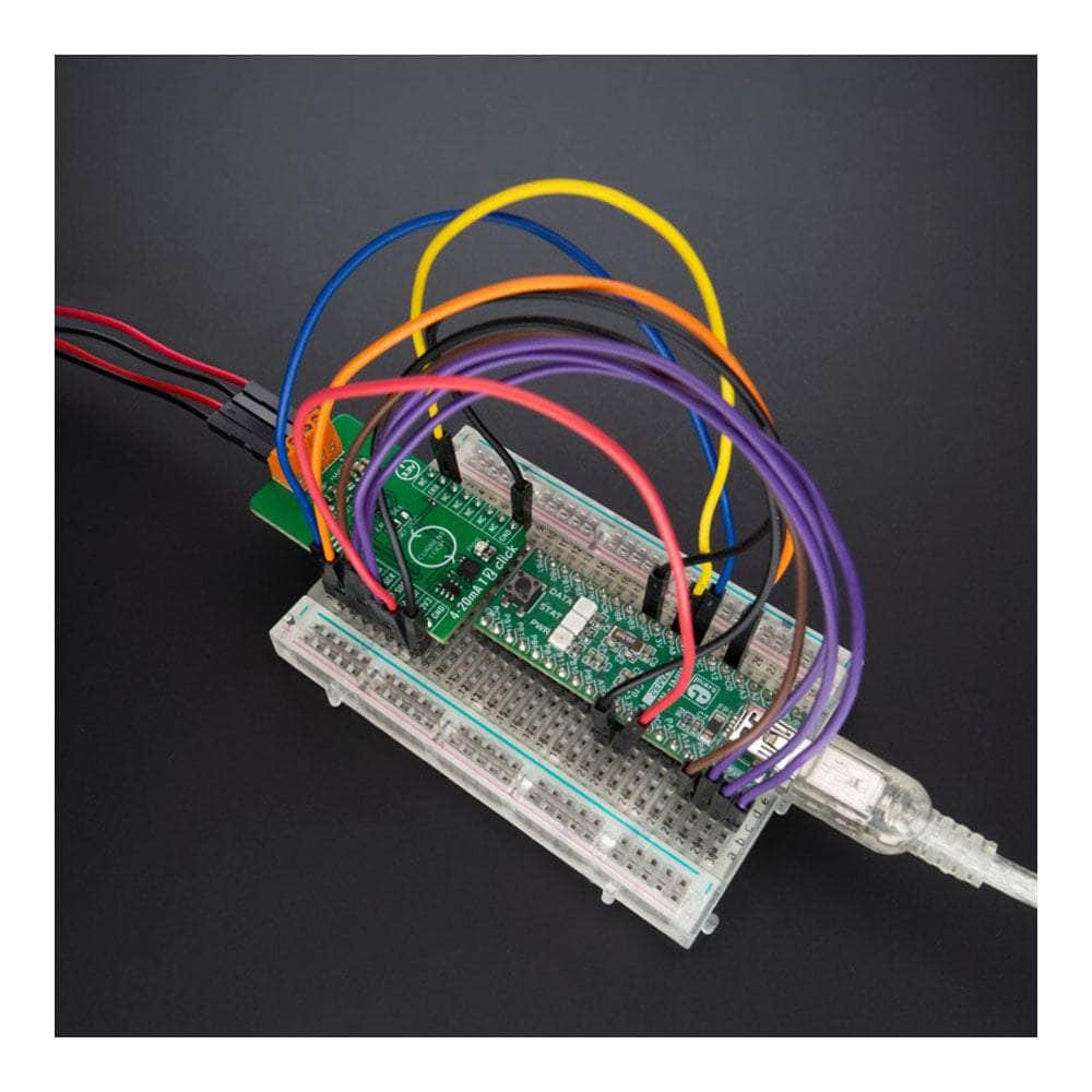
4-20 mA T 2 Click-Platine
Key Features
- Hohe Auflösung, Stromschleife nach Industriestandard, SPI-programmierbar, geringer Stromverbrauch, beim Einschalten programmierbarer Ausgangsstrom, Schleifenfehlererkennung und -meldung, HART-Modulatorschnittstelle und mehr
- Basierend auf dem DAC161S997 - 16-Bit-DAC für 4-20-mA-Schleifen von Texas Instruments
- Kann für 2-adrige 4-20-mA-Stromschleifensender, industrielle Prozesssteuerung, Sender mit geringem Stromverbrauch und mehr verwendet werden
- mikroBUS: SPI-Schnittstelle
Overview
Das 4-20 mA T 2 Click Board™: Übertragung von analogem Ausgangsstrom leicht gemacht!
Das 4-20 mA T 2 Click Board™ ist die ultimative Lösung für die Übertragung eines analogen Ausgangsstroms über eine 4-20 mA-Stromschleife nach Industriestandard. Diese kompakte Zusatzplatine wurde entwickelt, um Ihre Konnektivitätsanforderungen zu optimieren und bietet nahtlose Integration und zuverlässige Leistung.
Leistungsstarke Funktionen für optimale Leistung
Das Herzstück dieses bemerkenswerten Click Board™ ist der DAC161S997, ein stromsparender 16-Bit-ΣΔ-Digital-Analog-Wandler (DAC) vom branchenführenden Hersteller Texas Instruments. Mit seinen erweiterten Funktionen können Sie nichts weniger als außergewöhnliche Leistung erwarten.
Ein herausragendes Merkmal ist der programmierbare Einschaltzustand, mit dem Sie das Verhalten des Click Board™ bei Wiederherstellung der Stromversorgung anpassen können. Darüber hinaus bietet die Schleifenfehlererkennungs- und -meldefunktion wertvolle Einblicke in die Leistung Ihrer Stromschleife und gewährleistet so jederzeit einen reibungslosen Betrieb.
Das 4-20 mA T 2 Click Board™ vereinfacht die Datenübertragung und Konfiguration der DAC-Funktionen über eine einfache 4-adrige SPI-Schnittstelle. Dies bedeutet, dass Sie die Einstellungen mühelos an Ihre Anforderungen anpassen können und so wertvolle Zeit und Mühe sparen.
Effizienz und Flexibilität vereint
Der niedrige Stromverbrauch ist ein wichtiges Merkmal des 4-20 mA T 2 Click Board™. Dies gewährleistet einen energieeffizienten Betrieb, verlängert die Lebensdauer Ihres Systems und senkt die Gesamtstromkosten. Darüber hinaus können Sie dank der Kompatibilität mit der HART-Modulatorschnittstelle (Highway Addressable Remote Transducer) FSK-modulierte digitale Daten nahtlos in die 4-20 mA-Stromschleife einspeisen und so eine Welt voller Möglichkeiten erschließen.
Vielseitige Einsatzmöglichkeiten
Das 4-20 mA T 2 Click Board™ ist die perfekte Wahl für verschiedene Anwendungen. Egal, ob Sie mit 2-adrigen 4-20 mA-Stromschleifensendern, industriellen Prozesssteuerungssystemen oder Sendern mit geringem Stromverbrauch arbeiten, dieses Click Board™ bietet alles, was Sie brauchen.
Einfache Softwareentwicklung und -integration
Mit seiner mikroSDK-kompatiblen Bibliothek vereinfacht das 4-20mA T 2 Click Board™ die Softwareentwicklung, sodass Sie sich auf das Wesentliche konzentrieren können – Ihre Ideen zum Leben erwecken. Die Bibliothek umfasst eine Reihe von Funktionen, die den Entwicklungsprozess optimieren und ein reibungsloses und effizientes Erlebnis gewährleisten.
Wenn Sie sich für das 4-20 mA T 2 Click Board™ entscheiden, wählen Sie ein vollständig getestetes Produkt, das sich nahtlos in Ihr System integrieren lässt. Ausgestattet mit der zuverlässigen mikroBUS™-Buchse garantiert dieses Click Board™ eine mühelose Installation und Kompatibilität.
Geben Sie sich nicht mit weniger als Spitzenleistung zufrieden. Erleben Sie noch heute die Leistung und den Komfort des 4-20 mA T 2 Click Board™!
How Does The 4-20mA T 2 Click Board™ Work?
The 4-20mA T 2 Click Board™ is based on the DAC161S997, a low-power 16-bit ΣΔ digital-to-analog converter (DAC) from Texas Instruments, realized as a ΣΔ modulator. Next to ΣΔ DAC, the DAC161S997 also contains an internal ultra-low power voltage reference and an internal oscillator to reduce power and component count in compact loop-powered applications. This architecture, where DAC's output current represents a multiplied copy of the filtered modulator output, ensures an excellent linearity performance while minimizing the device's power consumption. In addition to an industry-standard 4-20 mA current loop over the LOOP terminal, the DAC161S997 also has the possibility of a simple Highway Addressable Remote Transducer (HART) modulator interfacing through an onboard HART TX terminal. It allows the injection of FSK-modulated digital data into the 4-20mA current loop.
The 4-20mA T 2 Click Board™ communicates with MCU using a 4-wire SPI serial interface with a maximum frequency of 10MHz, for data transfer and configuration of the DAC functions. The DAC161S997 supports both Mode 0 and Mode 3 of the SPI protocol. 4-20mA T 2 Click comes with an additional feature, as an interrupt, available on the ERR pin of the mikroBUS™ socket, the loop-error detection/reporting feature. By default, the DAC161S997 detects and reports several types of errors: loop error, SPI timeout error (channel error), frame error, and alarm current.
In the case of a fault condition or during the initial Power-Up sequence, the DAC161S997 will output current in either the upper or lower error current band. The band's choice is user-selectable via the appropriate position of an onboard jumper ERRL SEL, while the current error value is programmable through the SPI interface.
The 4-20mA T 2 Click Board™ can only operate with a 3.3V logic voltage level. The board must perform appropriate logic voltage level conversion before using MCUs with different logic levels. However, the Click board™ comes equipped with a library containing functions and an example code that can be used as a reference for further development.
SPECIFICATIONS
Type | Current |
Applications | It can be used for 2-wire 4-20mA current loop transmitters, industrial process control, low-power transmitters, and more |
On-board modules | DAC161S997 - 16-bit DAC for 4-20mA loops from Texas Instruments |
Key Features | High resolution, industry-standard current loop, SPI-programmable, low power consumption, Power-Up programmable output current, loop-error detection and reporting, HART modulator interfacing, and more |
Interface | SPI |
Compatibility | mikroBUS |
Click board size | M (42.9 x 25.4 mm) |
Input Voltage | 3.3V |
PINOUT DIAGRAM
This table shows how the pinout of the 4-20mA T 2 Click Board™ corresponds to the pinout on the mikroBUS™ socket (the latter shown in the two middle columns).
Notes | Pin | Pin | Notes | ||||
---|---|---|---|---|---|---|---|
NC | 1 | AN | PWM | 16 | NC | ||
NC | 2 | RST | INT | 15 | ERR | Loop-Error Interrupt | |
SPI Chip Select | CS | 3 | CS | RX | 14 | NC | |
SPI Clock | SCK | 4 | SCK | TX | 13 | NC | |
SPI Data OUT | SDO | 5 | MISO | SCL | 12 | NC | |
SPI Data IN | SDI | 6 | MOSI | SDA | 11 | NC | |
Power Supply | 3.3V | 7 | 3.3V | 5V | 10 | NC | |
Ground | GND | 8 | GND | GND | 9 | GND | Ground |
ONBOARD SETTINGS AND INDICATORS
Label | Name | Default | Description |
---|---|---|---|
LD1 | PWR | - | Power LED Indicator |
JP1 | ERRL SEL | Left | Power-Up Output Current Level Selection GND/VCC: Left position GND, Right position VCC |
4-20MA T 2 CLICK ELECTRICAL SPECIFICATIONS
Description | Min | Typ | Max | Unit |
---|---|---|---|---|
Supply Voltage | - | 3.3 | - | V |
Output Current | 4 | - | 20 | mA |
Software Support
We provide a library for the 4-20mA T 2 Click Board™ as well as a demo application (example), developed using MikroE compilers. The demo can run on all the main MikroE development boards.
The package can be downloaded/installed directly from NECTO Studio The package Manager(recommended), downloaded from our LibStock™ or found on MikroE Github account.
Library Description
This library contains API for the 4-20mA T 2 Click Board™ driver.
Key functions
-
c420mat2_set_output_current
4-20mA T 2 set output current function. -
c420mat2_get_status
4-20mA T 2 set status function. -
c420mat2_set_lower_limit
4-20mA T 2 set lower limit function.
Example Description
This example demonstrates the use of the 4-20mA T 2 Click Board™. This driver provides functions to configure analogue output current transfer over an industry standard 4-20mA current loop.
void application_task ( void )
{
if ( C420MAT2_OK == c420mat2_set_output_current( &c420mat2, 4.0 ) )
{
log_printf( &logger, " Loop Current: 4.0 mA rn" );
log_printf( &logger, " - - - - - - - - - - - - - - -rn" );
if ( C420MAT2_OK == c420mat2_get_status ( &c420mat2, &status ) )
{
display_status( );
}
Delay_ms( 5000 );
}
if ( C420MAT2_OK == c420mat2_set_output_current( &c420mat2, 10.0 ) )
{
log_printf( &logger, " Loop Current: 10.0 mA rn" );
log_printf( &logger, " - - - - - - - - - - - - - - -rn" );
if ( C420MAT2_OK == c420mat2_get_status ( &c420mat2, &status ) )
{
display_status( );
}
Delay_ms( 5000 );
}
if ( C420MAT2_OK == c420mat2_set_output_current( &c420mat2, 15.0 ) )
{
log_printf( &logger, " Loop Current: 15.0 mA rn" );
log_printf( &logger, " - - - - - - - - - - - - - - -rn" );
if ( C420MAT2_OK == c420mat2_get_status ( &c420mat2, &status ) )
{
display_status( );
}
Delay_ms( 5000 );
}
if ( C420MAT2_OK == c420mat2_set_output_current( &c420mat2, 20.0 ) )
{
log_printf( &logger, " Loop Current: 20.0 mA rn" );
log_printf( &logger, " - - - - - - - - - - - - - - -rn" );
if ( C420MAT2_OK == c420mat2_get_status ( &c420mat2, &status ) )
{
display_status( );
}
Delay_ms( 5000 );
}
}
The full application code, and ready to use projects can be installed directly from NECTO Studio. The package Manager(recommended), downloaded from our LibStock™ or found on MikroE Github account.
Other MikroE Libraries used in the example:
- MikroSDK.Board
- MikroSDK.Log
- Click.c420mAT2
Additional Notes and Information
Depending on the development board you are using, you may need USB UART Click Board™, USB UART 2 Click or RS232 Click to connect to your PC, for development systems with no UART to USB interface available on the board. UART terminal is available in all MikroE compilers.
MIKROSDK
The 4-20mA T 2 Click Board™ is supported with mikroSDK - MikroE Software Development Kit. To ensure proper operation of mikroSDK compliant Click board™ demo applications, mikroSDK should be downloaded from the LibStock and installed for the compiler you are using.
Frequently Asked Questions
Have a Question?
Be the first to ask a question about this.