


Mikroelektronika d.o.o.
ADC 21 Click-Platine
ADC 21 Click-Platine
SKU: MIKROE-5531
Verfügbarkeit für Abholungen konnte nicht geladen werden
Key Features
Overview
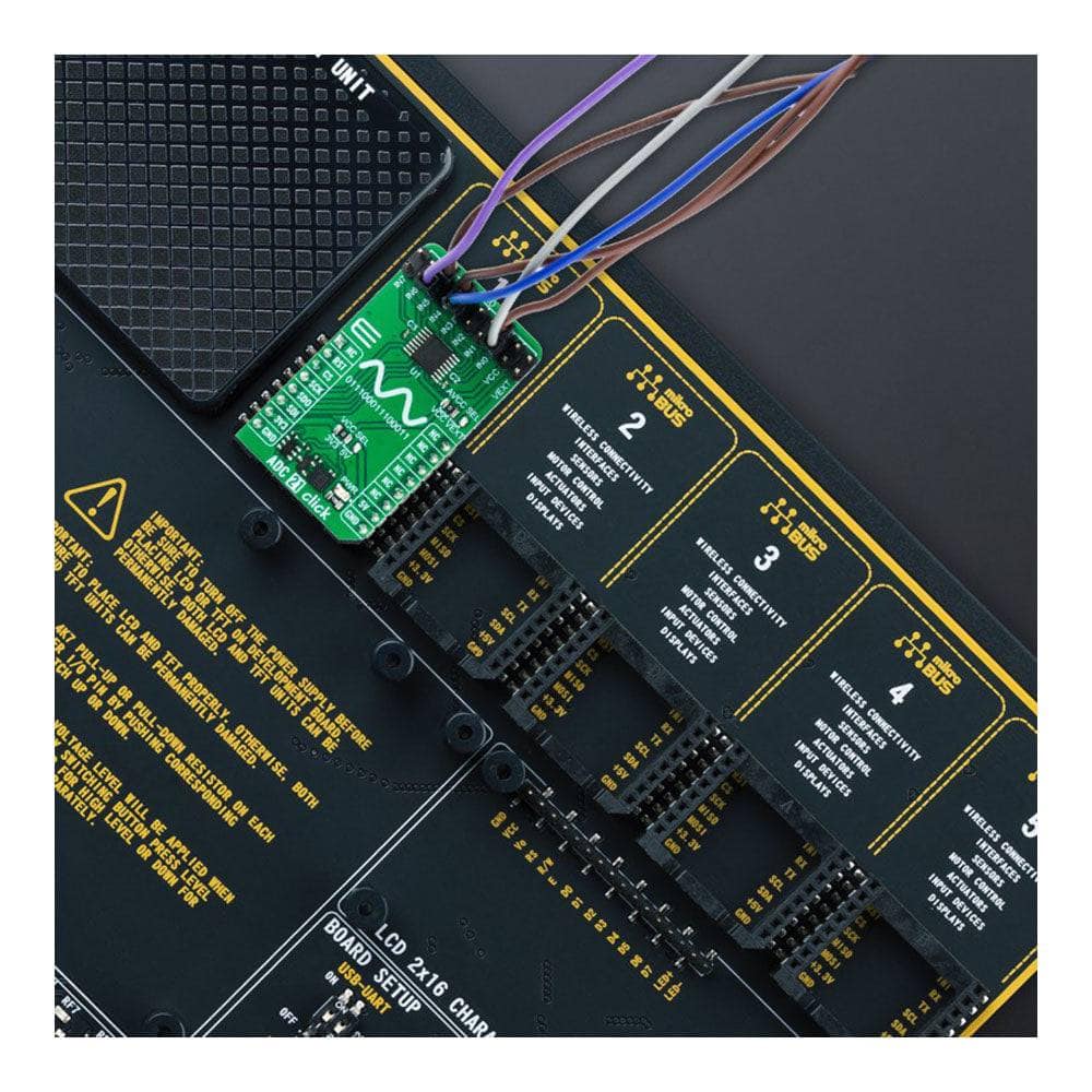
Introducing the ADC 21 Click Board™
Upgrade your analogue to digital conversion with the ADC 21 Click Board™ - a compact add-on board that delivers high accuracy and reliable performance for the most demanding applications. Whether you need remote data acquisition or instrumentation for industrial applications, the ADC 21 Click Board™ is the perfect solution for you.
Low-Power, High-Performance ADC
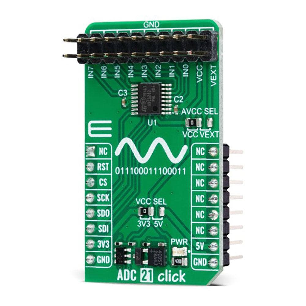
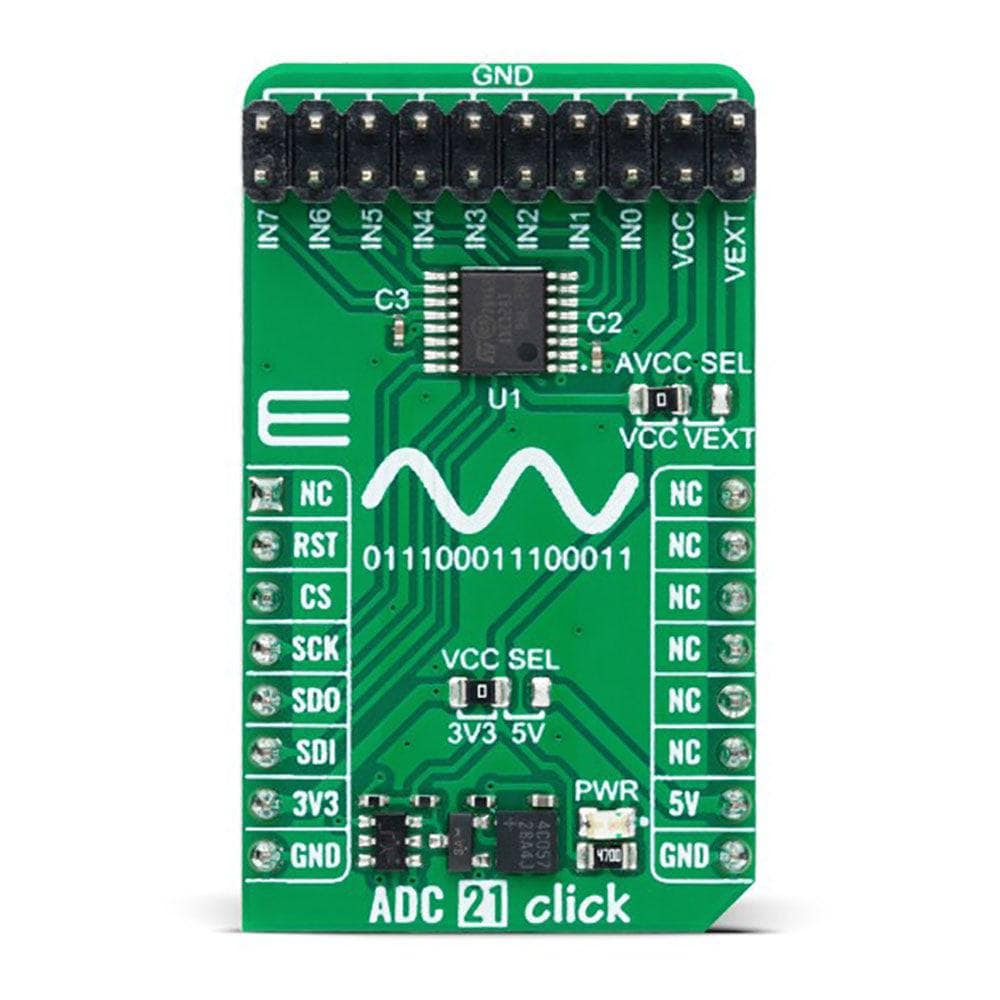
The ADC 21 Click Board™ features the ADC1283, a pure CMOS, eight-channel, 12-bit analogue-to-digital converter from STMicroelectronics. With a conversion rate of 50ksps to 200ksps, this low-power ADC delivers precise digital representation of analogue voltage. Its architecture is based on a successive approximation register with an internal track-and-hold cell, ensuring accurate and reliable performance.
Multiple Input Options
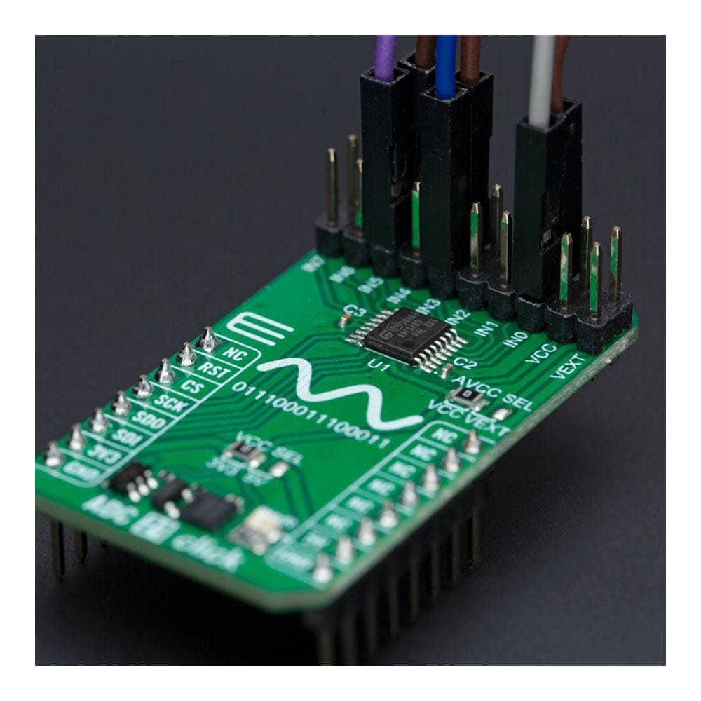
With eight single-ended multiplexed inputs, the ADC 21 Click Board™ offers versatile input options. The output serial data is straight binary and SPI-compatible, making it easy to integrate with other systems.
mikroSDK-Compliant Library for Easy Software Development
The ADC 21 Click Board™ is supported by a mikroSDK-compliant library, which includes functions that simplify software development. This means you can get up and running quickly without the need for complex programming.
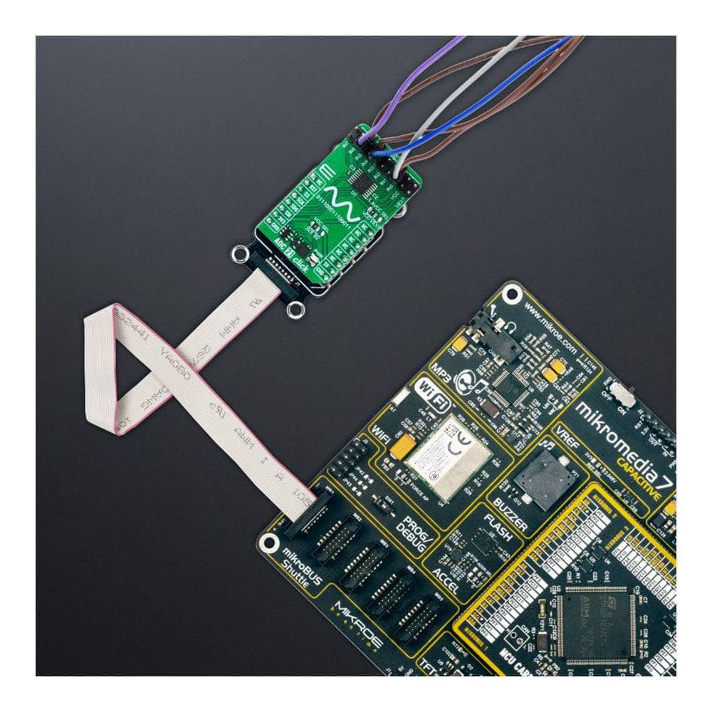
Fully Tested and Ready to Use
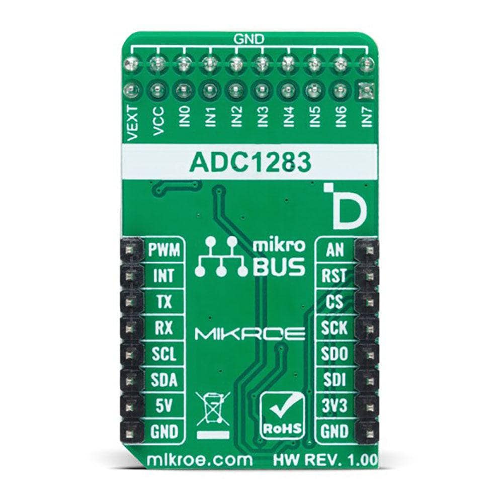
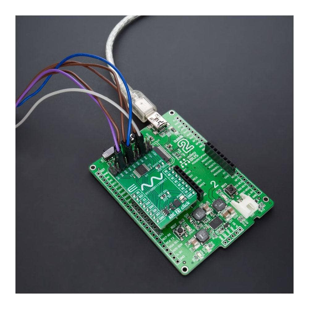
At Click Board™, we understand the importance of delivering reliable products. That's why the ADC 21 Click Board™ comes as a fully tested product, ready for use on any system equipped with the mikroBUS™ socket. You can trust that you're getting a high-quality product that will deliver accurate and reliable performance for all your analogue to digital conversion needs.
Downloads
Einführung des ADC 21 Click Board™
Aktualisieren Sie Ihre Analog-Digital-Konvertierung mit dem ADC 21 Click Board™ – einer kompakten Zusatzplatine, die hohe Genauigkeit und zuverlässige Leistung für die anspruchsvollsten Anwendungen bietet. Ganz gleich, ob Sie eine Remote-Datenerfassung oder Instrumentierung für industrielle Anwendungen benötigen, das ADC 21 Click Board™ ist die perfekte Lösung für Sie.
Leistungsstarker ADC mit geringem Stromverbrauch
Das ADC 21 Click Board™ verfügt über den ADC1283, einen reinen CMOS-, Achtkanal-, 12-Bit-Analog-Digital-Wandler von STMicroelectronics. Mit einer Konvertierungsrate von 50 kSps bis 200 kSps liefert dieser stromsparende ADC eine präzise digitale Darstellung der analogen Spannung. Seine Architektur basiert auf einem sukzessiven Approximationsregister mit einer internen Track-and-Hold-Zelle, die eine genaue und zuverlässige Leistung gewährleistet.
Mehrere Eingabeoptionen
Mit acht unsymmetrischen Multiplex-Eingängen bietet das ADC 21 Click Board™ vielseitige Eingabeoptionen. Die seriellen Ausgangsdaten sind rein binär und SPI-kompatibel, sodass sie sich leicht in andere Systeme integrieren lassen.
mikroSDK-kompatible Bibliothek für einfache Softwareentwicklung
Das ADC 21 Click Board™ wird von einer mikroSDK-kompatiblen Bibliothek unterstützt, die Funktionen enthält, die die Softwareentwicklung vereinfachen. Dies bedeutet, dass Sie schnell loslegen können, ohne dass komplexe Programmierung erforderlich ist.
Umfassend getestet und sofort einsatzbereit
Bei Click Board™ wissen wir, wie wichtig es ist, zuverlässige Produkte zu liefern. Deshalb ist das ADC 21 Click Board™ ein vollständig getestetes Produkt, das für den Einsatz auf jedem System mit der MikroBUS™-Buchse bereit ist. Sie können darauf vertrauen, dass Sie ein hochwertiges Produkt erhalten, das genaue und zuverlässige Leistung für alle Ihre Anforderungen an die Analog-Digital-Konvertierung bietet.
| General Information | |
|---|---|
Part Number (SKU) |
MIKROE-5531
|
Manufacturer |
|
| Physical and Mechanical | |
Weight |
0.02 kg
|
| Other | |
EAN |
8606027384561
|
Frequently Asked Questions
Have a Question?
-
Is the ADC 21 Click Board™ a fully tested product?
Yes, the ADC 21 Click Board™ comes as a fully tested product, ready for use on a system equipped with a mikroBUS™ socket.
-
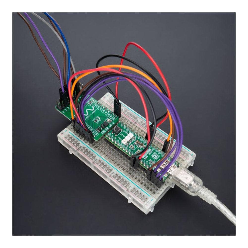
What is the mikroBUS™ socket, and is the ADC 21 Click Board™ compatible with it?
The mikroBUS™ socket is a standardised interface used by MikroElektronika for their Click boards™, providing easy integration with development boards and other hardware. The ADC 21 Click Board™ is designed to work with a system equipped with a mikroBUS™ socket, ensuring seamless compatibility.
-
What is the mikroSDK and how does it support the ADC 21 Click Board™?
The mikroSDK is a software development kit that provides a set of libraries, drivers, and examples for MikroElektronika hardware products. The ADC 21 Click Board™ is supported by a mikroSDK-compliant library, which includes functions that simplify software development, making it easier to integrate the board into your projects.
-
What types of applications is the ADC 21 Click Board™ suitable for?
The ADC 21 Click Board™ is suitable for a wide range of applications, including general-purpose remote data acquisition, instrumentation, and various industrial applications.
-
What are the key features of the ADC 21 Click Board™?
The ADC 21 Click Board™ offers: Eight single-ended multiplexed inputs Output serial data that is straight binary and SPI-compatible High accuracy for demanding applications Compatibility with mikroSDK-compliant libraries for simplified software development
-
What is the ADC 21 Click Board™?
The ADC 21 Click Board™ is a compact add-on board designed to convert an analogue voltage into a digital representation. It features the ADC1283, a low-power, eight-channel, pure CMOS 12-bit analogue-to-digital converter from STMicroelectronics.