


Mikroelektronika d.o.o.
MUX 5 Click-Platine
MUX 5 Click-Platine
SKU: MIKROE-5423
Verfügbarkeit für Abholungen konnte nicht geladen werden


Key Features
Overview
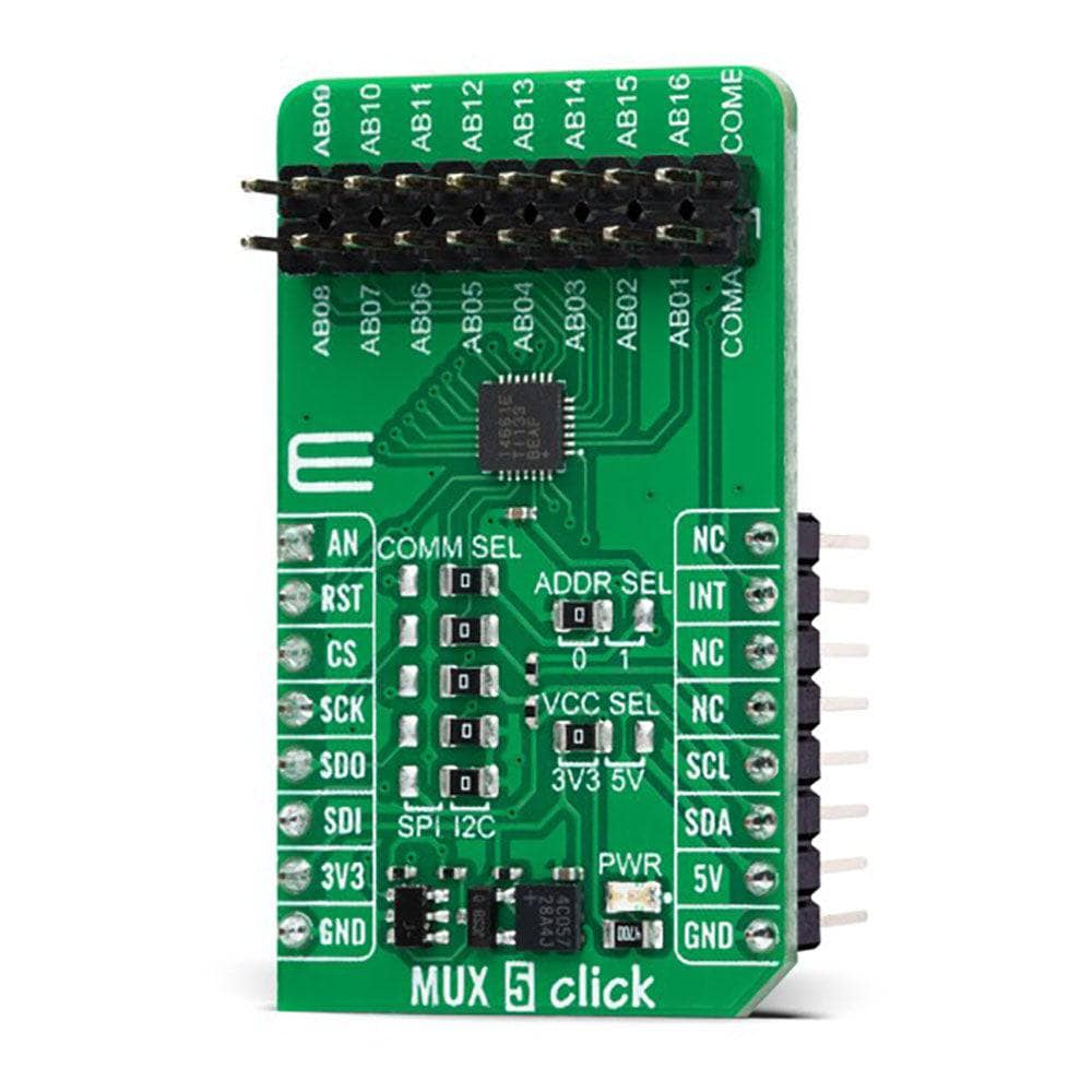
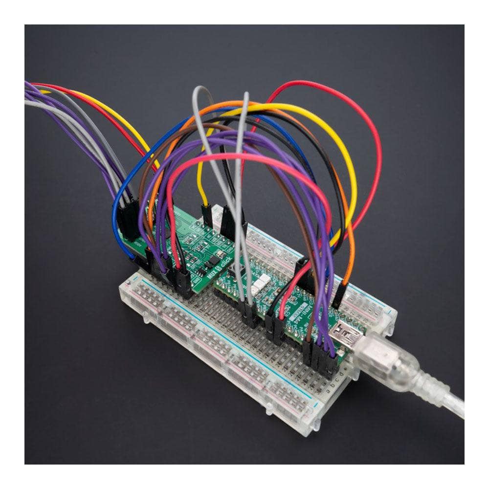
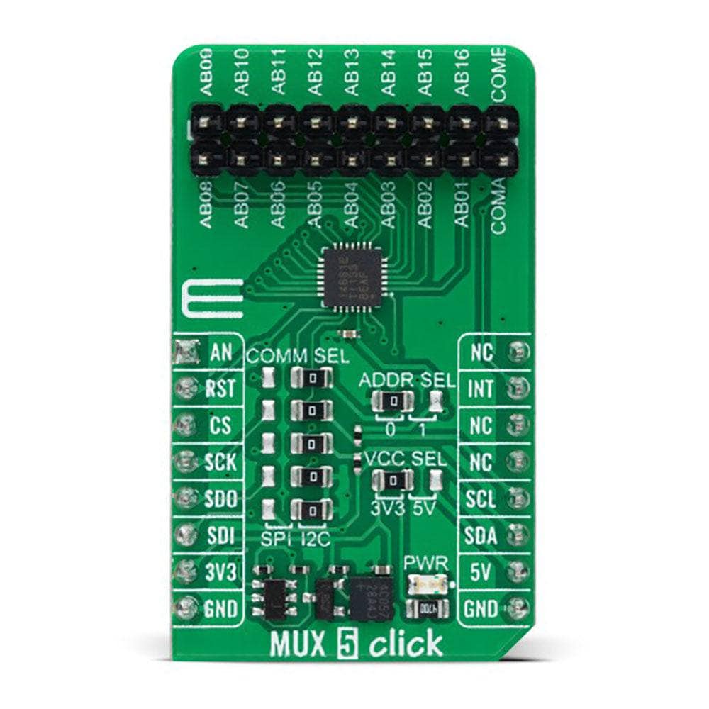
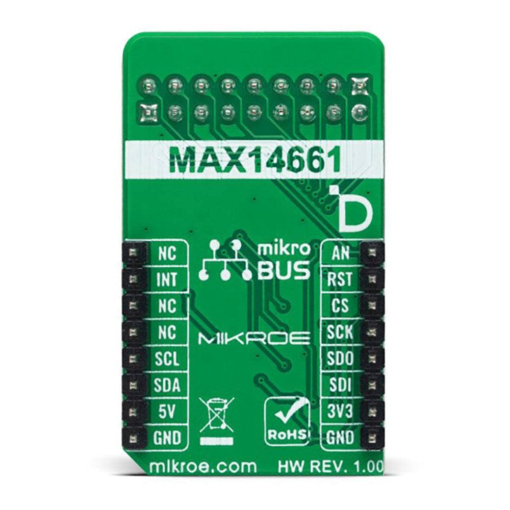
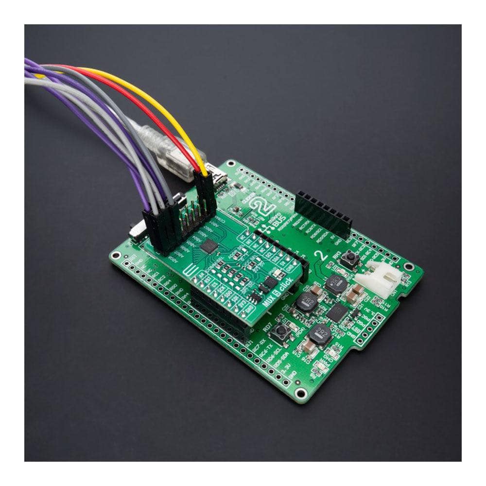
The MUX 5 Click Board™ is a compact add-on board that contains a precise multiplexing solution. This board features the MAX14661, a serially controlled, dual-channel analogue multiplexer from Analog Devices, allowing any of the 16 pins to be connected to either common pin simultaneously in any combination. The MAX14661 features Beyond-the-Rails™ capability that allows ±5.5V signals to be passed with any supply configuration alongside a configurable host interface that supports SPI and I2C serial communications. Both modes provide individual control of each independent switch so that any combination of switches can be applied. This Click board™ is designed to support various multiplexing applications like system diagnostics, data acquisition, signal switching, and many more.
The MUX 5 Click Board™ is supported by a mikroSDK-compliant library, which includes functions that simplify software development. This Click board™ comes as a thoroughly tested product, ready to be used on a system equipped with the mikroBUS™ socket.
Downloads
Das MUX 5 Click Board™ ist eine kompakte Zusatzplatine, die eine präzise Multiplexing-Lösung enthält. Diese Platine verfügt über den MAX14661, einen seriell gesteuerten, zweikanaligen analogen Multiplexer von Analog Devices, mit dem jeder der 16 Pins gleichzeitig in beliebiger Kombination mit einem der gemeinsamen Pins verbunden werden kann. Das MAX14661 verfügt über Beyond-the-Rails™-Funktionen, die die Übertragung von ±5,5-V-Signalen mit jeder Versorgungskonfiguration ermöglichen, sowie über eine konfigurierbare Hostschnittstelle, die SPI- und I2C-Seriellkommunikation unterstützt. Beide Modi ermöglichen die individuelle Steuerung jedes unabhängigen Schalters, sodass jede beliebige Schalterkombination angewendet werden kann. Dieses Click Board™ wurde entwickelt, um verschiedene Multiplexing-Anwendungen wie Systemdiagnose, Datenerfassung, Signalumschaltung und vieles mehr zu unterstützen.
Das MUX 5 Click Board™ wird von einer mikroSDK-kompatiblen Bibliothek unterstützt, die Funktionen enthält, die die Softwareentwicklung vereinfachen. Dieses Click Board™ ist ein gründlich getestetes Produkt und kann auf einem System verwendet werden, das mit der mikroBUS™-Buchse ausgestattet ist.
| General Information | |
|---|---|
Part Number (SKU) |
MIKROE-5423
|
Manufacturer |
|
| Physical and Mechanical | |
Weight |
0.02 kg
|
| Other | |
EAN |
8606027386343
|
Frequently Asked Questions
Have a Question?
Be the first to ask a question about this.