


Mikroelektronika d.o.o.
LBAND RTK Click-Platine
LBAND RTK Click-Platine
Verfügbarkeit für Abholungen konnte nicht geladen werden
Key Features:
- Hohe Präzision, hohe Leistung, L-Band-GNSS-Korrektur, zentimetergenaue Genauigkeit, professionelle Qualität, hohe Skalierbarkeit für verschiedene Anwendungen, wählbare Schnittstelle, Integration mit u-blox F9-Empfängern, Sicherheitsfunktionen und mehr
- Basierend auf dem NEO-D9S-00B - Satellitendatenempfänger für L-Band-Korrekturübertragung von u-blox
- Einsetzbar für diverse Korrekturdienste im industriellen Bereich
- mikroBUS: I2C-, SPI-, UART-Schnittstellen plus USB
Das LBAND RTK Click Board™ ist eine kompakte Zusatzplatine, die globalen und einfachen Zugriff auf Satelliten-GNSS-Korrekturen im L-Band bietet. Diese Platine verfügt über den NEO-D9S-00B, einen professionellen Satellitendatenempfänger für L-Band-Korrekturübertragungen von u-blox. Der NEO-D9S-00B arbeitet in einem Frequenzbereich von 1525 MHz bis 1559 MHz, dekodiert die Satellitenübertragung und gibt einen Korrekturstrom aus, wodurch ein hochpräziser GNSS-Empfänger Genauigkeiten bis auf Zentimeterebene erreichen kann. Außerdem kann er den GNSS-Korrekturdaten-Lieferkanal neben erweiterten Sicherheitsfunktionen wie Signatur und Anti-Jamming auswählen. Dieses Click Board™ kann für verschiedene Korrekturdienste für industrielle und professionelle Anwendungen konfiguriert werden.
Das LBAND RTK Click Board™ wird von einer mikroSDK-kompatiblen Bibliothek unterstützt, die Funktionen enthält, die die Softwareentwicklung vereinfachen. Dieses Click Board™ wird als vollständig getestetes Produkt geliefert und ist bereit für den Einsatz auf einem System, das mit der mikroBUS™-Buchse ausgestattet ist.


How Does The LBAND RTK Click Board™ Work?
The LBAND RTK Click Board™ is based on the NEO-D9S-00B, a satellite data receiver for L-band correction broadcast from u-blox, which can be configured for use with various correction services. Operating in a frequency range from 1525MHz to 1559MHz, the NEO-D9S-00B decodes the satellite transmission and outputs a correction stream, enabling a high-precision GNSS receiver to reach accuracies down to centimeter level. An independent stream of correction data, delivered over satellite L-band, ensures high availability of position output. Simultaneously, it reduces dependence on a cellular connection for the correction service provided over IP. Besides, it implements advanced security features such as signature and anti-jamming mechanisms.
In addition to accessing the broadcast data stream, the NEO-D9S-00B also eliminates the need for a dedicated delivery channel per user, making it flexible for different markets and applications. It is configurable for use with correction data of various providers and service levels, ensuring precision in multiple regions globally, as well as coverage across continents. This Click board™ can be easily integrated with other GNSS receivers from the u-blox F9 platform, such as GNSS RTK Click boards™ from our offer, providing a complete solution built with less design effort.
The LBAND RTK Click Board™ communicates with the host MCU using the UART interface at 115200bps as its default communication protocol but also has other interfaces, such as SPI and I2C. The interface is selected by positioning SMD jumpers labelled COMM SEL in an appropriate position. When choosing the SPI communication, with the correct selection of the COMM SEL jumpers, it is also necessary to populate the DSEL jumper to configure the interface pins as SPI. In the default state, the jumper labelled as DSEL is unpopulated. In the case of using only this Click board™ alone via the I2C interface, it is necessary to populate I2C pull-up resistors (R2 and R3). Remove these resistors when using LBAND RTK in combination with other GNSS RTK boards. An additional header holds an optional UART interface, which can provide correction data directly to a GNSS receiver.
The USB interface, compatible with USB version 2.0 (Full Speed, 12 Mbit/s), can be used for communication as an alternative to the UART. Also, the USB port can be used as an additional power supply if you need the Click board™ to be a standalone device. In this case, the main module supply is provided by an onboard regulator, the NCV8705, providing the necessary 3.3V for its proper operation. The receiver also can enter a Safe-Boot mode. When the jumper labelled SFBT is populated, the receiver starts in Safe-Boot mode, and the L-band operation is disabled. During Safe-Boot mode, only the main UART interface is possible.
In addition to these features, this board also uses several mikroBUS™ pins. EIN pin routed to the AN pin of the mikroBUS™ socket is used as an external interrupt feature activated through a population of the R6 0Ω resistor. The RST pin routed on the PWM pin of the mikroBUS™ socket provides the general reset ability.
The LBAND RTK Click Board™ possesses the SMA antenna connector for connecting the appropriate antenna that MikroE offers, such as GNSS L-Band Active Antenna. This antenna easily allows positioning in space, supporting GNSS L-Band frequencies. This Click board™ can be operated only with a 5V logic voltage level. The board must perform appropriate logic voltage level conversion before using MCUs with different logic levels. However, the Click board™ comes equipped with a library containing functions and an example code that can be used as a reference for further development.
SPECIFICATIONS
| Type | GPS/GNSS |
| Applications | Can be used for various correction services for industrial applications |
| On-board modules | NEO-D9S-00B - satellite data receiver for L-band correction broadcast from u-blox |
| Key Features | High precision, high performance, L-band GNSS correction, centimeter-level accuracy, professional-grade, high scalability for various applications, selectable interface, integration with u-blox F9 receivers, security features, and more |
| Interface | I2C,SPI,UART,USB |
| Compatibility | mikroBUS |
| Click board size | L (57.15 x 25.4 mm) |
| Input Voltage | 5V |
PINOUT DIAGRAM
This table shows how the pinout of the LBAND RTK Click Board™ corresponds to the pinout on the mikroBUS™ socket (the latter shown in the two middle columns).
| Notes | Pin | Pin | Notes | ||||
|---|---|---|---|---|---|---|---|
| External Interrupt | EN | 1 | AN | PWM | 16 | RST | Reset |
| NC | 2 | RST | INT | 15 | NC | ||
| SPI Chip Select | CS | 3 | CS | RX | 14 | TX | UART TX |
| SPI Clock | SCK | 4 | SCK | TX | 13 | RX | UART RX |
| SPI Data OUT | SDO | 5 | MISO | SCL | 12 | SCL | I2C Clock |
| SPI Data IN | SDI | 6 | MOSI | SDA | 11 | SDA | I2C Data |
| NC | 7 | 3.3V | 5V | 10 | 5V | Power Supply | |
| Ground | GND | 8 | GND | GND | 9 | GND | Ground |
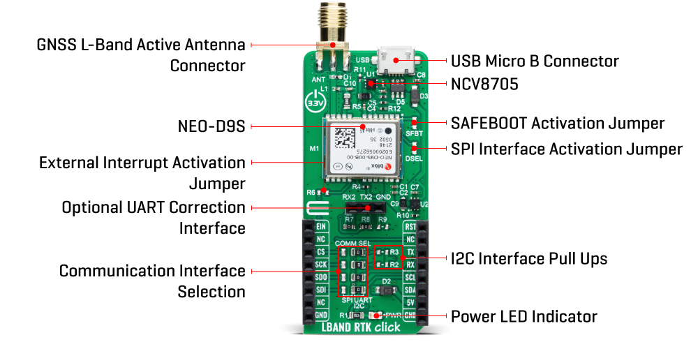
ONBOARD SETTINGS AND INDICATORS
| Label | Name | Default | Description |
|---|---|---|---|
| LD1 | PWR | - | Power LED Indicator |
| JP1-JP4 | COMM SEL | Right | Communication Interface Selection SPI/UART,I2C: Left position SPI, Right position UART,I2C |
| SFBT | SFBT | Unpopulated | SAFEBOOT Activation Jumper |
| DSEL | DSEL | Unpopulated | SPI Interface Activation Jumper |
| R6 | R6 | Unpopulated | External Interrupt Activation Jumper |
| J1 | RX2/TX2 | Populated | Optional UART Correction Interface Header |
| R2-R3 | R2-R3 | Unpopulated | I2C Pull-Up Resistors |
LBAND RTK CLICK ELECTRICAL SPECIFICATIONS
| Description | Min | Typ | Max | Unit |
|---|---|---|---|---|
| Receiver inputs voltage range | - | 5 | - | V |
| Frequency Range | 1525 | - | 1559 | MHz |
| Acquisition Sensitivity | - | -133 | - | dBm |
| Time To First Frame (TTF at 2400bps) | <10 | - | - | sec |
Specifications
Dimensions
LBAND RTK Click-Platine
Software Support
We provide a library for the LBAND RTK Click Board™ as well as a demo application (example), developed using MikroE compilers. The demo can run on all the main MikroE development boards.
The package can be downloaded/installed directly from NECTO Studio The package Manager(recommended), downloaded from our LibStock™ or found on MikroE Github account.
Library Description
This library contains API for LBAND RTK Click Board™ driver.
Key functions
-
lbandrtk_set_default_pmp_cfgThis function sets the Point to multipoint (PMP) to default configuration to RAM layer. -
lbandrtk_get_pmp_cfgThis function reads the Point to multipoint (PMP) configuration from RAM layer. -
lbandrtk_read_ubx_frameThis function waits for an UBX frame message to arrive and reads it.
Example Description
This example demonstrates the use of LBAND RTK Click Board™ by setting the Point to multipoint (PMP) configuration and waiting for the UBX-RXM-PMP message, then parsing it and displaying on the USB UART.
void application_task ( void )
 {
     if ( LBANDRTK_OK == lbandrtk_read_ubx_frame ( &lbandrtk, &lbandrtk.frame ) )
     {
         if ( ( LBANDRTK_CLASS_ID_UBX_RXM == lbandrtk.frame.class_id ) && ( LBANDRTK_MSG_ID_UBX_RXM_PMP == lbandrtk.frame.msg_id ) )
         {
             log_printf( &logger, " -------- UBX-RXM-PMP -------rn" );
             uint16_t num_bytes_user_data = LBANDRTK_UBX_RXM_PMP_MAX_USER_DATA; // Number of bytes for user data for message version 0
             log_printf( &logger, " Version: %urn", ( uint16_t ) lbandrtk.frame.payload[ 0 ] );
             log_printf( &logger, " Time tag [ms]: %lurn",
                         ( ( uint32_t ) lbandrtk.frame.payload[ 7 ] << 24 ) | ( ( uint32_t ) lbandrtk.frame.payload[ 6 ] << 16 ) |
                         ( ( uint16_t ) lbandrtk.frame.payload[ 5 ] << 8 ) | lbandrtk.frame.payload[ 4 ] );
             log_printf( &logger, " Unique word: 0x%.8LX%.8LXrn",
                         ( ( uint32_t ) lbandrtk.frame.payload[ 15 ] << 24 ) | ( ( uint32_t ) lbandrtk.frame.payload[ 14 ] << 16 ) |
                         ( ( uint16_t ) lbandrtk.frame.payload[ 13 ] << 8 ) | lbandrtk.frame.payload[ 12 ],
                         ( ( uint32_t ) lbandrtk.frame.payload[ 11 ] << 24 ) | ( ( uint32_t ) lbandrtk.frame.payload[ 10 ] << 16 ) |
                         ( ( uint16_t ) lbandrtk.frame.payload[ 9 ] << 8 ) | lbandrtk.frame.payload[ 8 ] );
             log_printf( &logger, " Unique word bit errors: %urn", ( uint16_t ) lbandrtk.frame.payload[ 19 ] );
             // Check the received message version
             if ( lbandrtk.frame.payload[ 0 ] )
             {
                 log_printf( &logger, " FEC bits : %urn", ( ( uint16_t ) lbandrtk.frame.payload[ 21 ] << 8 ) | lbandrtk.frame.payload[ 20 ] );
                 log_printf( &logger, " Eb/N0 [dB] : %.3frn", lbandrtk.frame.payload[ 22 ] * LBANDRTK_UBX_RXM_PMP_EBN0_SCALE );
             }
             else
             {
                 log_printf( &logger, " FEC bits : %urn", ( ( uint16_t ) lbandrtk.frame.payload[ 525 ] << 8 ) | lbandrtk.frame.payload[ 524 ] );
                 log_printf( &logger, " Eb/N0 [dB] : %.3frn", lbandrtk.frame.payload[ 526 ] * LBANDRTK_UBX_RXM_PMP_EBN0_SCALE );
             }
             log_printf( &logger, "rn Service ID : %urn", ( ( uint16_t ) lbandrtk.frame.payload[ 17 ] << 8 ) | lbandrtk.frame.payload[ 16 ] );
             log_printf( &logger, " Spare byte: %urn", ( uint16_t ) lbandrtk.frame.payload[ 18 ] );
             // Check the received message version
             if ( lbandrtk.frame.payload[ 0 ] )
             {
                 // Get number of bytes for user data for message version 1
                 num_bytes_user_data = ( ( uint16_t ) lbandrtk.frame.payload[ 3 ] << 8 ) | lbandrtk.frame.payload[ 2 ];
                 if ( num_bytes_user_data > LBANDRTK_UBX_RXM_PMP_MAX_USER_DATA )
                 {
                     num_bytes_user_data = LBANDRTK_UBX_RXM_PMP_MAX_USER_DATA;
                 }
                 log_printf( &logger, " User data bytes: %urn", num_bytes_user_data );
                 log_printf( &logger, " User data:rn" );
                 for ( uint16_t cnt = 0; cnt < num_bytes_user_data; cnt++ )
                 {
                     if ( 0 == ( cnt % 20 ) )
                     {
                         log_printf( &logger, "rn" );
                     }
                     log_printf( &logger, "%.2X ", ( uint16_t ) lbandrtk.frame.payload[ 24 + cnt ] );
                 }
             }
             else
             {
                 log_printf( &logger, " User data bytes: %urn", num_bytes_user_data );
                 log_printf( &logger, " User data:rn" );
                 for ( uint16_t cnt = 0; cnt < num_bytes_user_data; cnt++ )
                 {
                     if ( 0 == ( cnt % 20 ) )
                     {
                         log_printf( &logger, "rn" );
                     }
                     log_printf( &logger, " %.2X", ( uint16_t ) lbandrtk.frame.payload[ 20 + cnt ] );
                 }
             }
             log_printf( &logger, "rn ----------------------------rnn" );
             Delay_ms ( 100 );
         }
         else
         {
             log_printf( &logger, " ---- UBX FRAME RECEIVED ----rn" );
             log_printf( &logger, " Class ID: 0x%.2Xrn", ( uint16_t ) lbandrtk.frame.class_id );
             log_printf( &logger, " Message ID: 0x%.2Xrn", ( uint16_t ) lbandrtk.frame.msg_id );
             log_printf( &logger, " Payload length: %urn", lbandrtk.frame.payload_len );
             log_printf( &logger, " Payload:" );
             for ( uint16_t cnt = 0; cnt < lbandrtk.frame.payload_len; cnt++ )
             {
                 if ( 0 == ( cnt % 20 ) )
                 {
                     log_printf( &logger, "rn" );
                 }
                 log_printf( &logger, " %.2X", ( uint16_t ) lbandrtk.frame.payload[ cnt ] );
             }
             log_printf( &logger, "rn ----------------------------rnn" );
             Delay_ms ( 100 );
         }
     }
 }
The full application code, and ready to use projects can be installed directly from NECTO Studio The package Manager(recommended), downloaded from our LibStock™ or found on MikroE Github account.
Other MikroE Libraries used in the example:
- MikroSDK.Board
- MikroSDK.Log
- Click.LBANDRTK
Additional Notes and Information
Depending on the development board you are using, you may need USB UART Click Board™, USB UART 2 Click or RS232 Click to connect to your PC, for development systems with no UART to USB interface available on the board. UART terminal is available in all MikroE compilers.
MIKROSDK
The LBAND RTK Click Board™ is supported with mikroSDK - MikroE Software Development Kit. To ensure proper operation of mikroSDK compliant Click board™ demo applications, mikroSDK should be downloaded from the LibStock and installed for the compiler you are using.
LBAND RTK Click-Platine
Frequently Asked Questions
Have a Question?
Be the first to ask a question about this.