


Mikroelektronika d.o.o.
Expand 14 Klickbrett
Expand 14 Klickbrett
SKU: MIKROE-5241
Verfügbarkeit für Abholungen konnte nicht geladen werden


Key Features
Overview
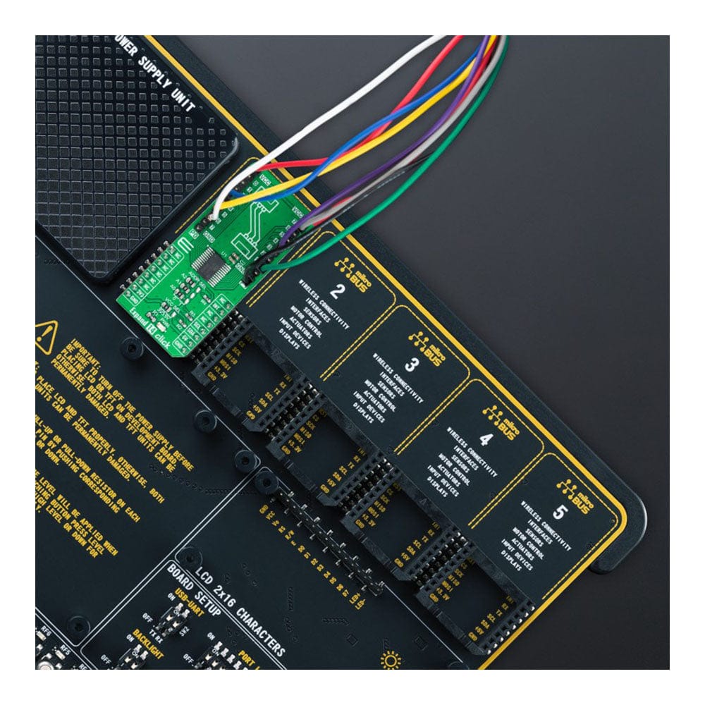
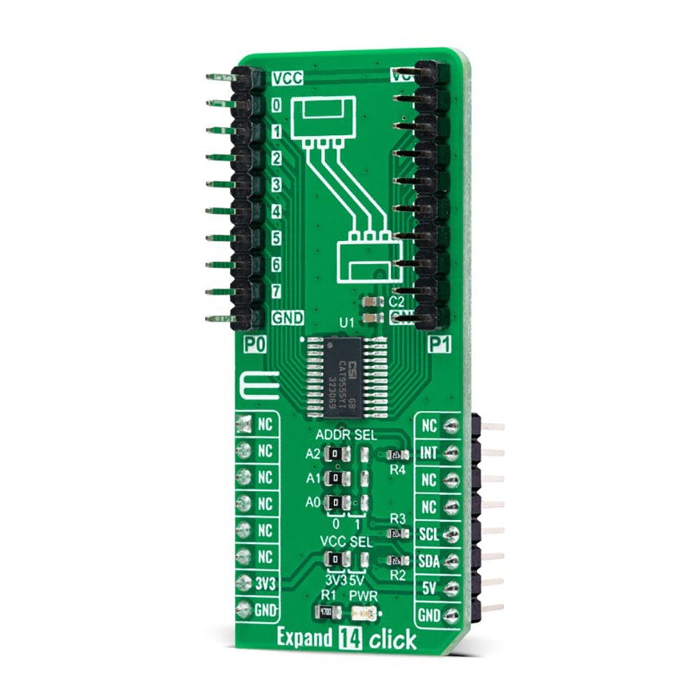
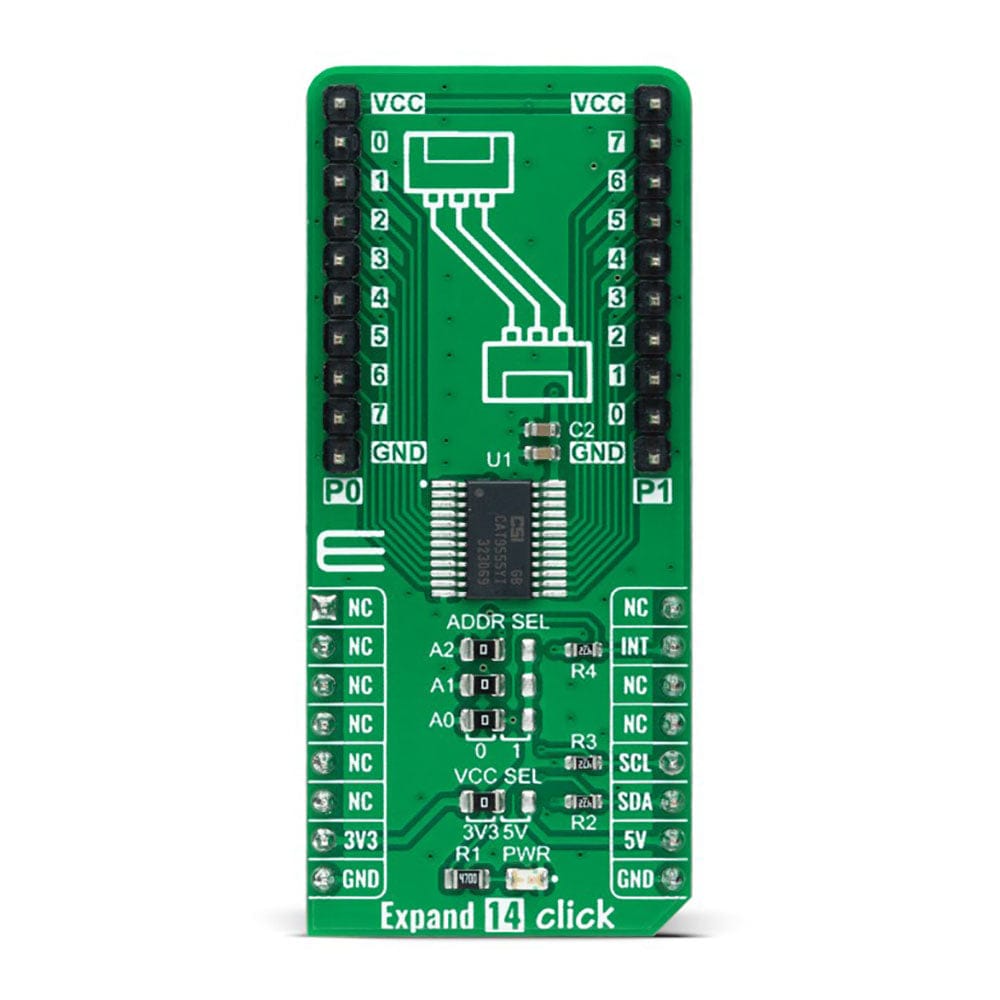
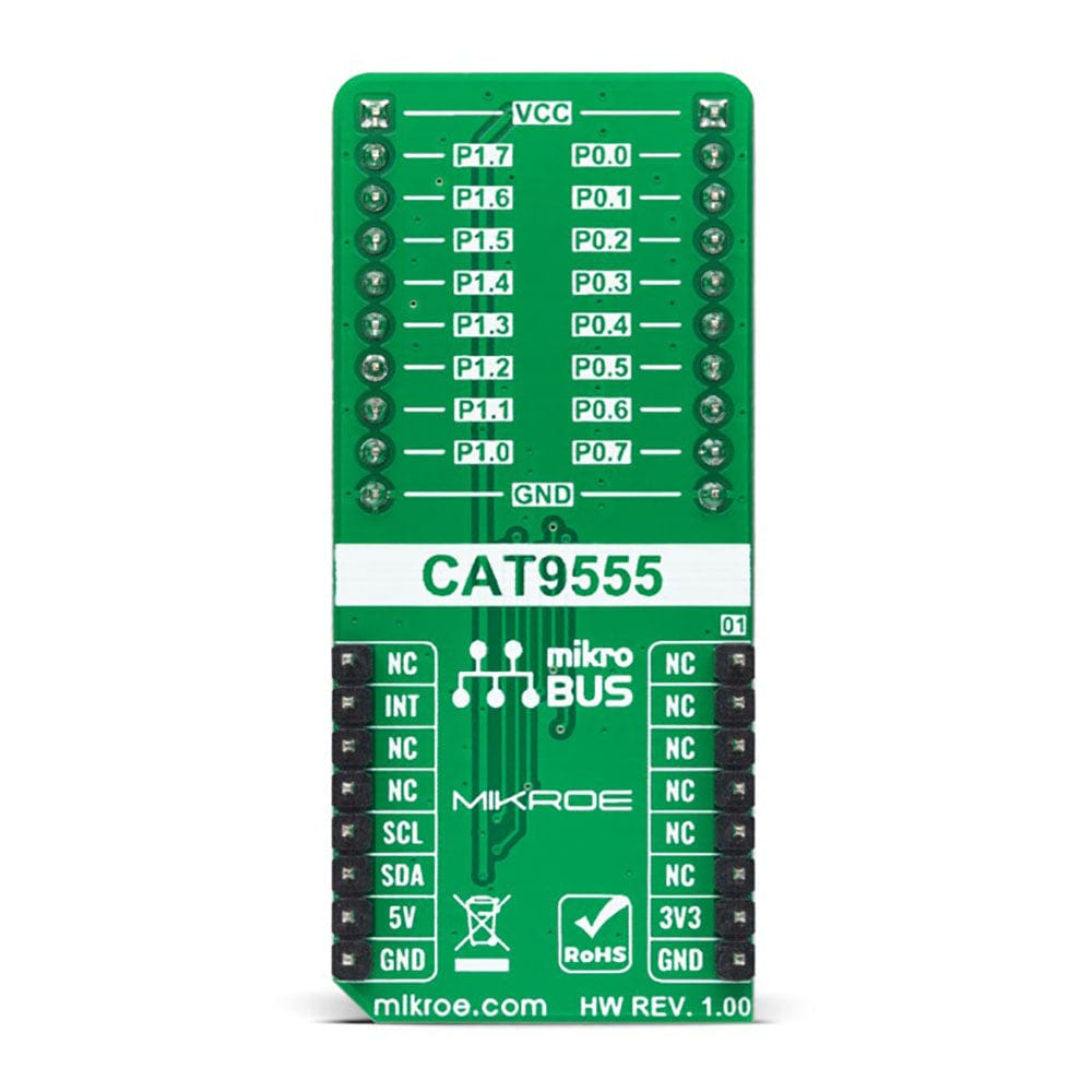
The Expand 14 Click Board™ is a compact add-on board that contains a multi-port I/O expander. This board features the CAT9555, a CMOS device that provides 16-bit parallel input/output port expansion from ON Semiconductor. The CAT9555 contains two 8-bit configuration ports (input or output), input, output, and polarity inversion registers, alongside an I2C-compatible serial interface. Any sixteen I/Os can be configured as an input or output by writing to the configuration register. It also features an active-low interrupt output, indicating to the host controller that an input state has been changed. This Click board™ provides a simple solution when additional I/Os are needed while keeping interconnections to a minimum in system monitoring applications, industrial controllers, portable equipment, and many more.
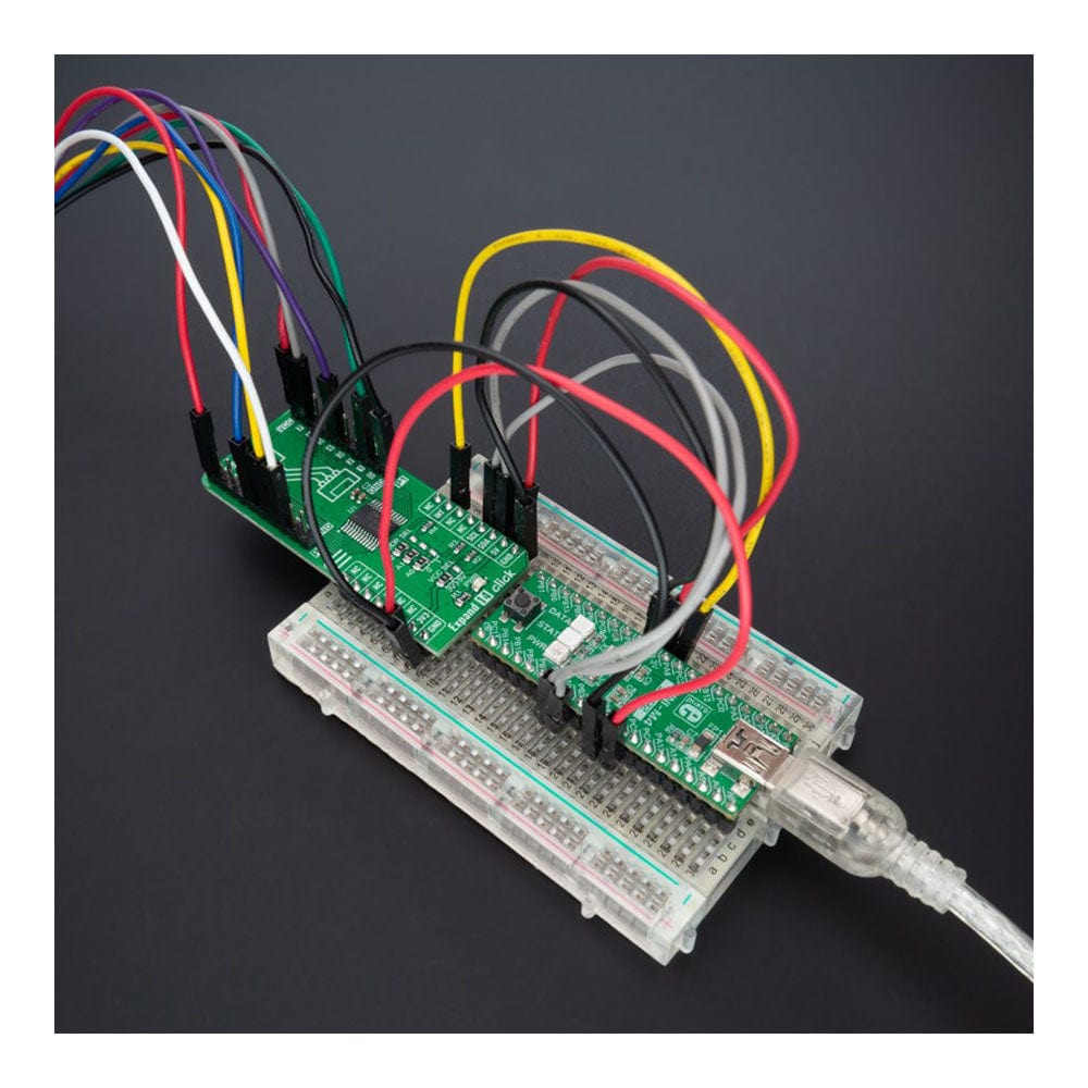
The Expand 14 Click Board™ is supported by a mikroSDK compliant library, including functions that simplify software development. This Click board™ comes as a thoroughly tested product, ready to be used on a system equipped with the mikroBUS™ socket.
Downloads
Das Expand 14 Click Board™ ist eine kompakte Zusatzplatine, die einen Multiport-E/A-Expander enthält. Diese Platine verfügt über das CAT9555, ein CMOS-Gerät, das eine 16-Bit-Parallel-Eingangs-/Ausgangsanschlusserweiterung von ON Semiconductor bietet. Das CAT9555 enthält zwei 8-Bit-Konfigurationsanschlüsse (Eingang oder Ausgang), Eingangs-, Ausgangs- und Polaritätsumkehrregister sowie eine I2C-kompatible serielle Schnittstelle. Alle 16 E/As können durch Schreiben in das Konfigurationsregister als Eingang oder Ausgang konfiguriert werden. Es verfügt außerdem über einen Active-Low-Interrupt-Ausgang, der dem Host-Controller anzeigt, dass ein Eingangszustand geändert wurde. Dieses Click Board™ bietet eine einfache Lösung, wenn zusätzliche E/As benötigt werden, während die Verbindungen in Systemüberwachungsanwendungen, Industriesteuerungen, tragbaren Geräten und vielem mehr auf ein Minimum beschränkt bleiben.
Das Expand 14 Click Board™ wird von einer mikroSDK-kompatiblen Bibliothek unterstützt, einschließlich Funktionen, die die Softwareentwicklung vereinfachen. Dieses Click Board™ ist ein gründlich getestetes Produkt und kann auf einem System verwendet werden, das mit der mikroBUS™-Buchse ausgestattet ist.
| General Information | |
|---|---|
Part Number (SKU) |
MIKROE-5241
|
Manufacturer |
|
| Physical and Mechanical | |
Weight |
0.02 kg
|
| Other | |
EAN |
8606027388194
|
Frequently Asked Questions
Have a Question?
Be the first to ask a question about this.