


Mikroelektronika d.o.o.
Winkel 7 Klickbrett
Winkel 7 Klickbrett
SKU: MIKROE-5196
Verfügbarkeit für Abholungen konnte nicht geladen werden
Key Features
Overview
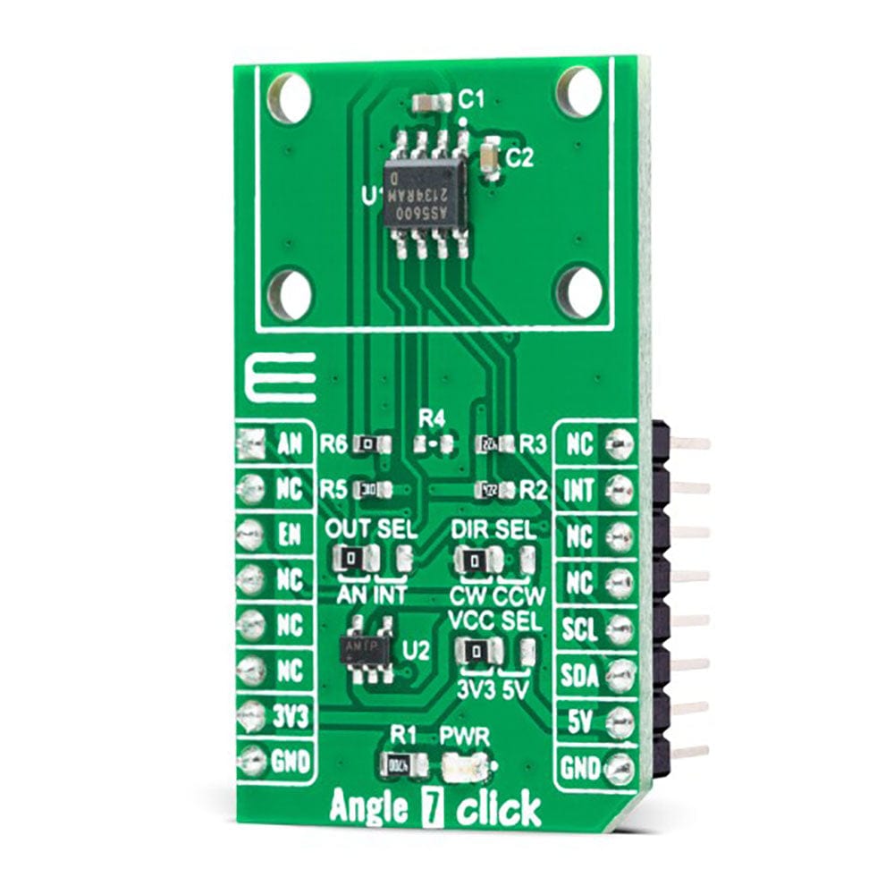
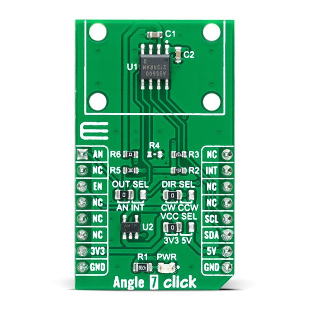
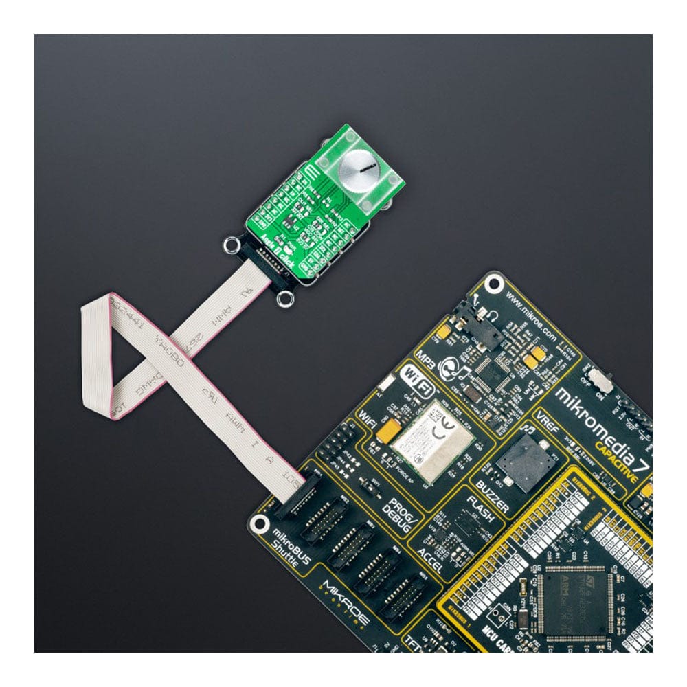
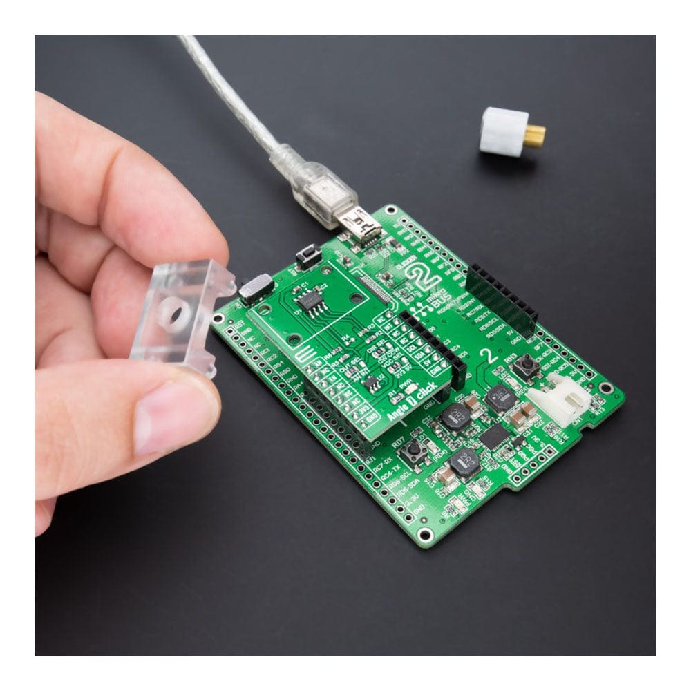
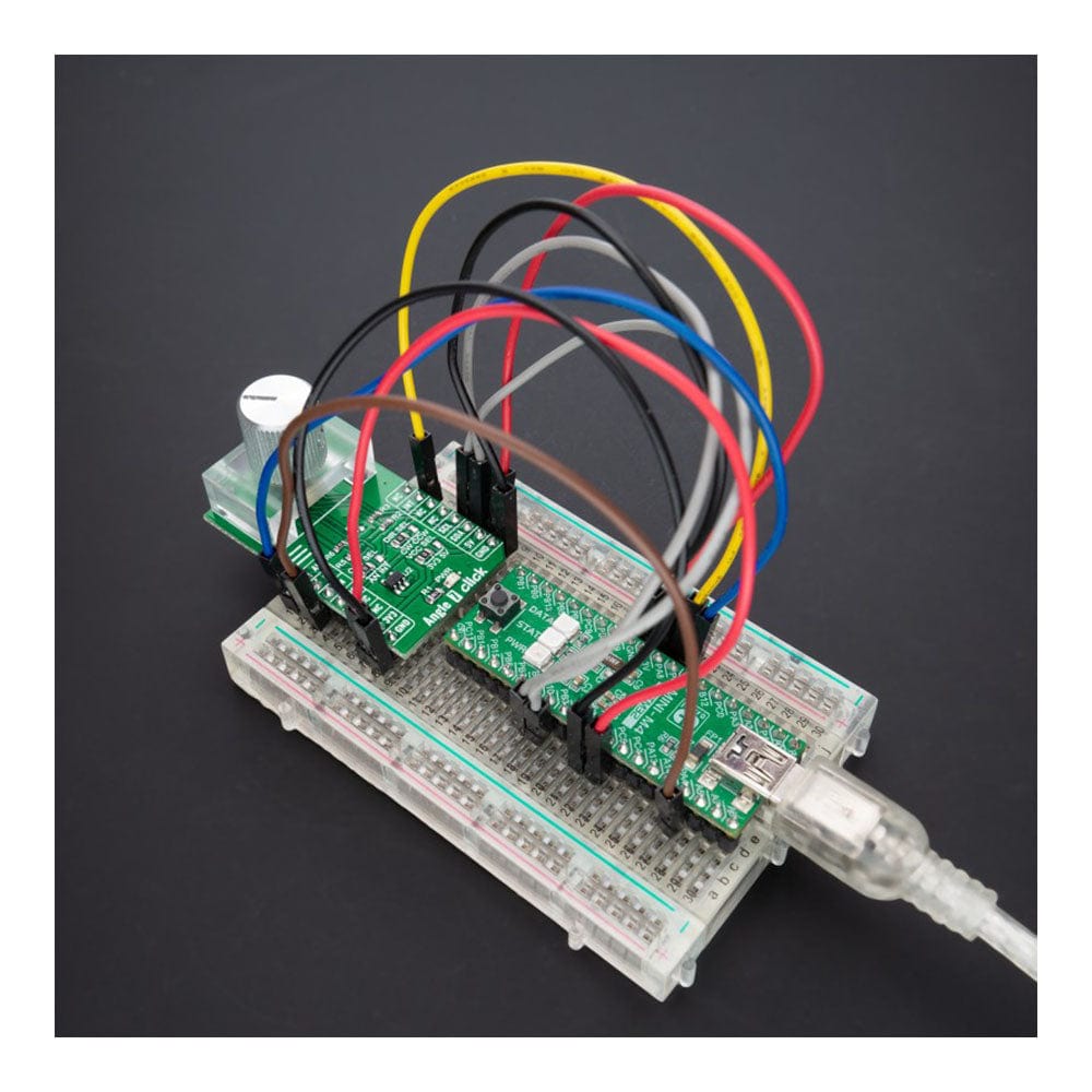
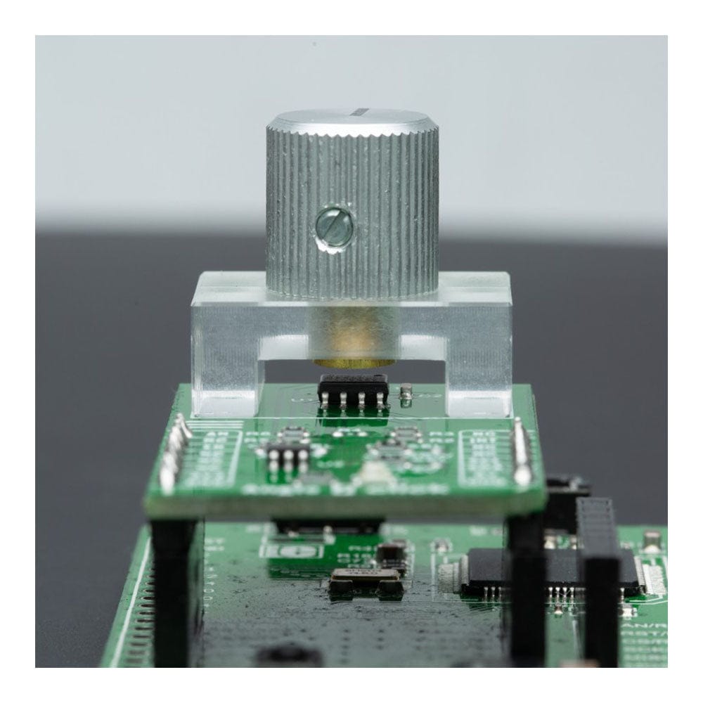
The Angle 7 Click Board™ is a compact add-on board that detects the absolute angular position of a permanent magnet. This board features the AS5600, a programmable Hall-based rotary magnetic position sensor with a high-resolution 12-bit analogue or PWM output from AMS AG. Based on planar Hall technology, this sensor measures the orthogonal component of the flux density (Bz) from an external magnet while rejecting stray magnetic fields. The default range of the output is from 18 to 360 degrees, where the full resolution of the device can be applied to a smaller range by programming a zero angle (start position) and a maximum angle (Stop position) through the I2C interface used for configuration and user programming of non-volatile parameters. This Click board™ is suitable for contactless potentiometers, contactless knobs, RC servos, and other angular position measurement solutions.
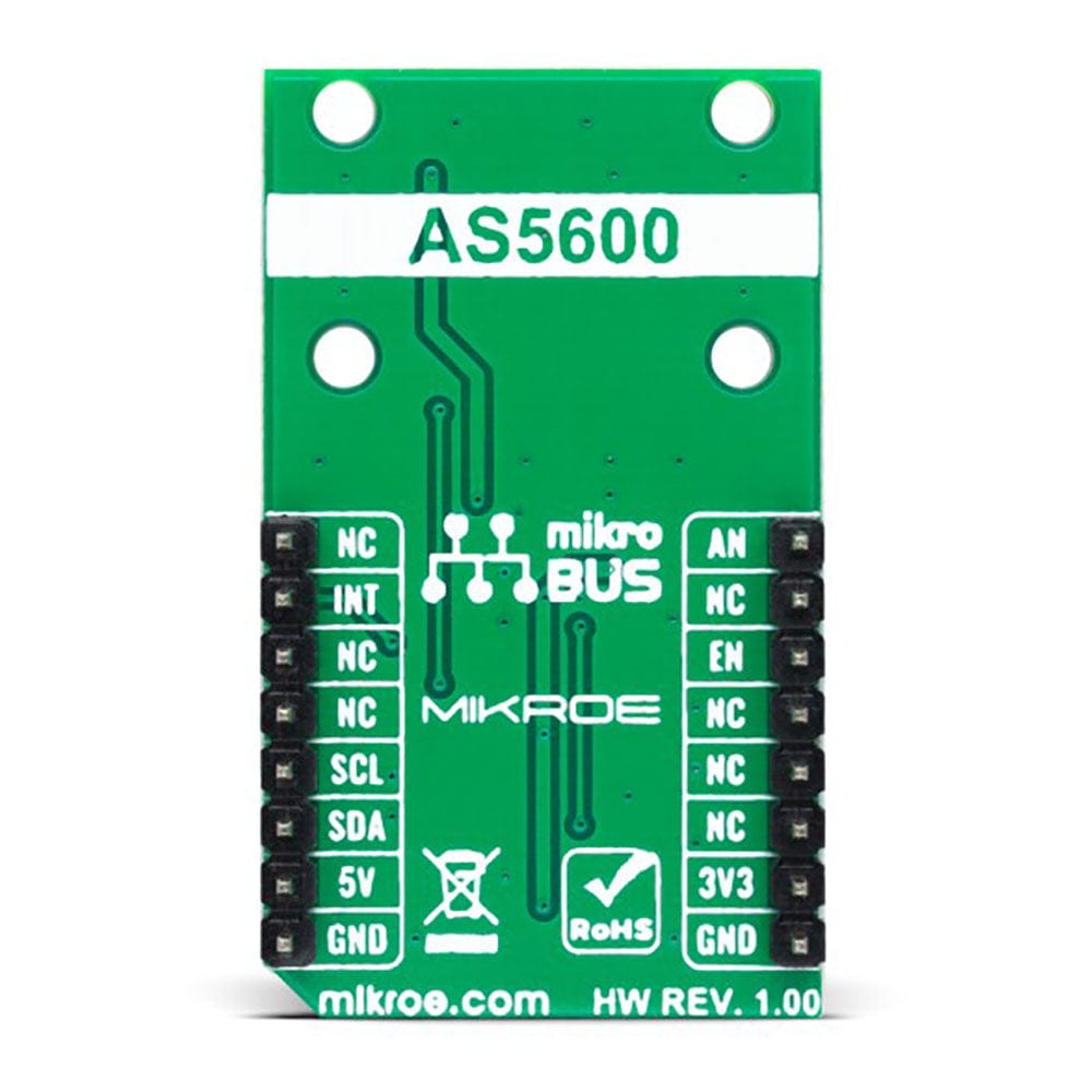
The Angle 7 Click Board™ is supported by a mikroSDK compliant library, which includes functions that simplify software development. This Click board™ comes as a fully tested product, ready to be used on a system equipped with the mikroBUS™ socket.
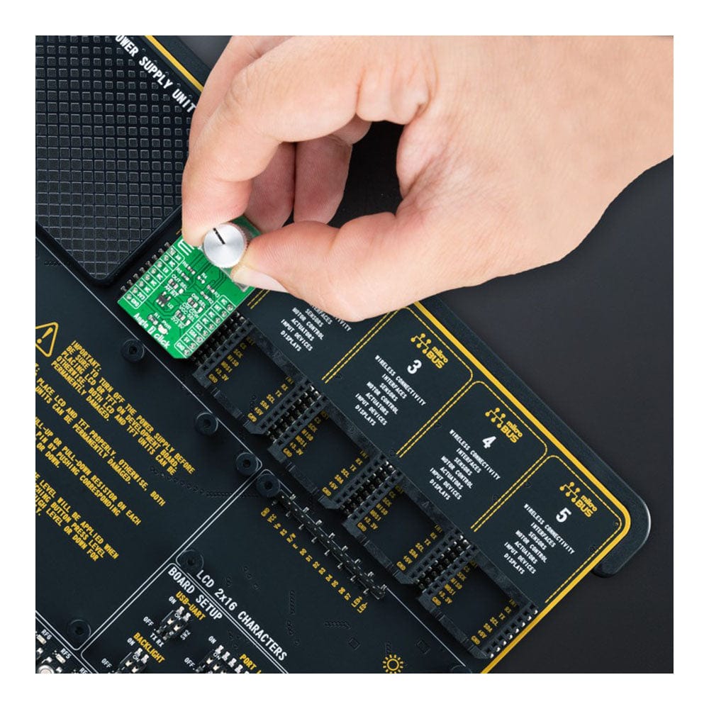
Note: The Click Board does not include the magnet, holder or control knob. This is shown as an example application.
Downloads
Das Angle 7 Click Board™ ist eine kompakte Zusatzplatine, die die absolute Winkelposition eines Permanentmagneten erkennt. Diese Platine verfügt über den AS5600, einen programmierbaren Hall-basierten rotierenden magnetischen Positionssensor mit einem hochauflösenden 12-Bit-Analog- oder PWM-Ausgang von AMS AG. Basierend auf planarer Hall-Technologie misst dieser Sensor die orthogonale Komponente der Flussdichte (Bz) von einem externen Magneten und weist Streumagnetfelder zurück. Der Standardbereich des Ausgangs liegt zwischen 18 und 360 Grad, wobei die volle Auflösung des Geräts auf einen kleineren Bereich angewendet werden kann, indem ein Nullwinkel (Startposition) und ein Maximalwinkel (Stoppposition) über die I2C-Schnittstelle programmiert werden, die für die Konfiguration und Benutzerprogrammierung nichtflüchtiger Parameter verwendet wird. Dieses Click Board™ ist für kontaktlose Potentiometer, kontaktlose Knöpfe, RC-Servos und andere Lösungen zur Winkelpositionsmessung geeignet.
Das Angle 7 Click Board™ wird von einer mikroSDK-kompatiblen Bibliothek unterstützt, die Funktionen enthält, die die Softwareentwicklung vereinfachen. Dieses Click Board™ wird als vollständig getestetes Produkt geliefert und ist bereit für den Einsatz auf einem System, das mit der mikroBUS™-Buchse ausgestattet ist.
Hinweis: Das Click Board enthält weder Magnet, Halter noch Bedienknopf. Dies wird als Beispielanwendung angezeigt.
| General Information | |
|---|---|
Part Number (SKU) |
MIKROE-5196
|
Manufacturer |
|
| Physical and Mechanical | |
Weight |
0.02 kg
|
| Other | |
EAN |
8606027388279
|
Frequently Asked Questions
Have a Question?
Be the first to ask a question about this.