


Mikroelektronika d.o.o.
Analoge MUX 5 Click-Platine
Analoge MUX 5 Click-Platine
SKU: MIKROE-5120
Verfügbarkeit für Abholungen konnte nicht geladen werden
Key Features
Overview
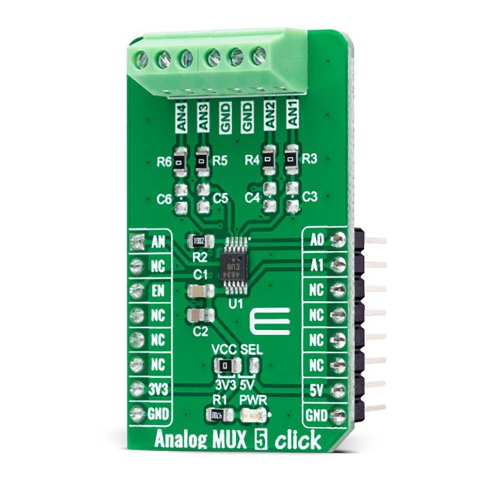
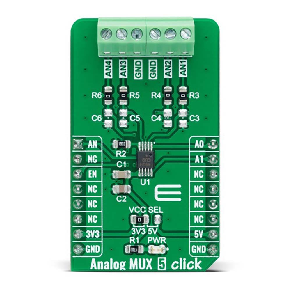
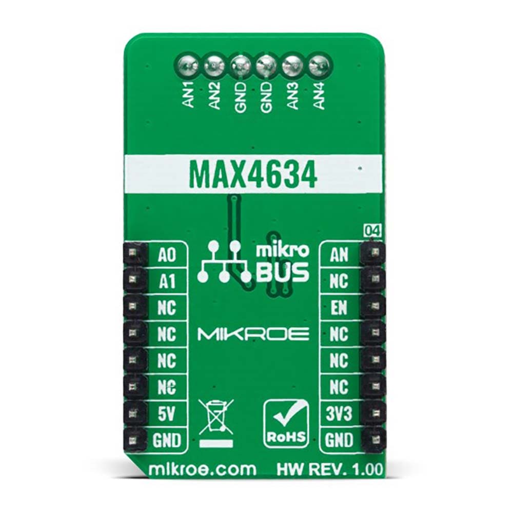
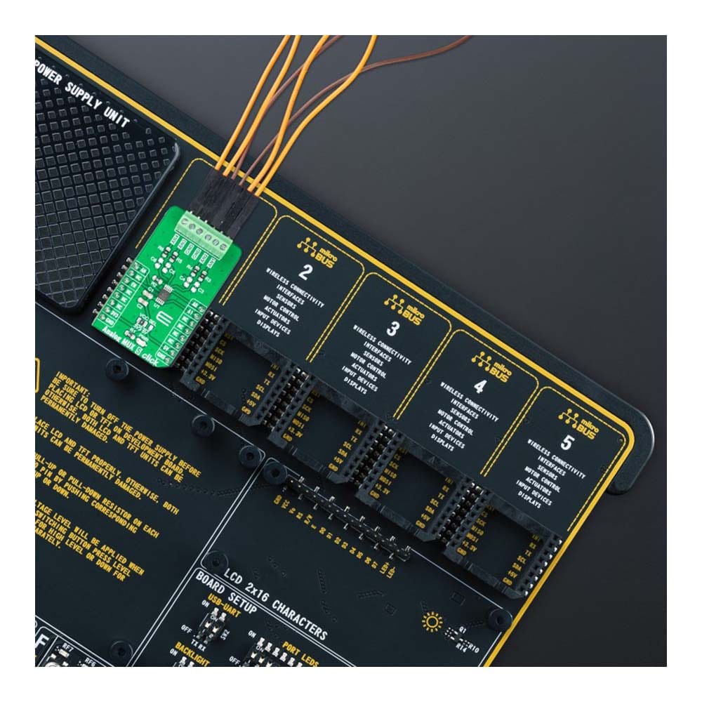
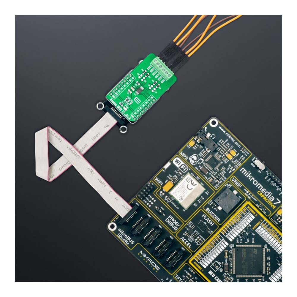
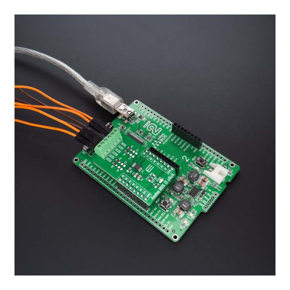
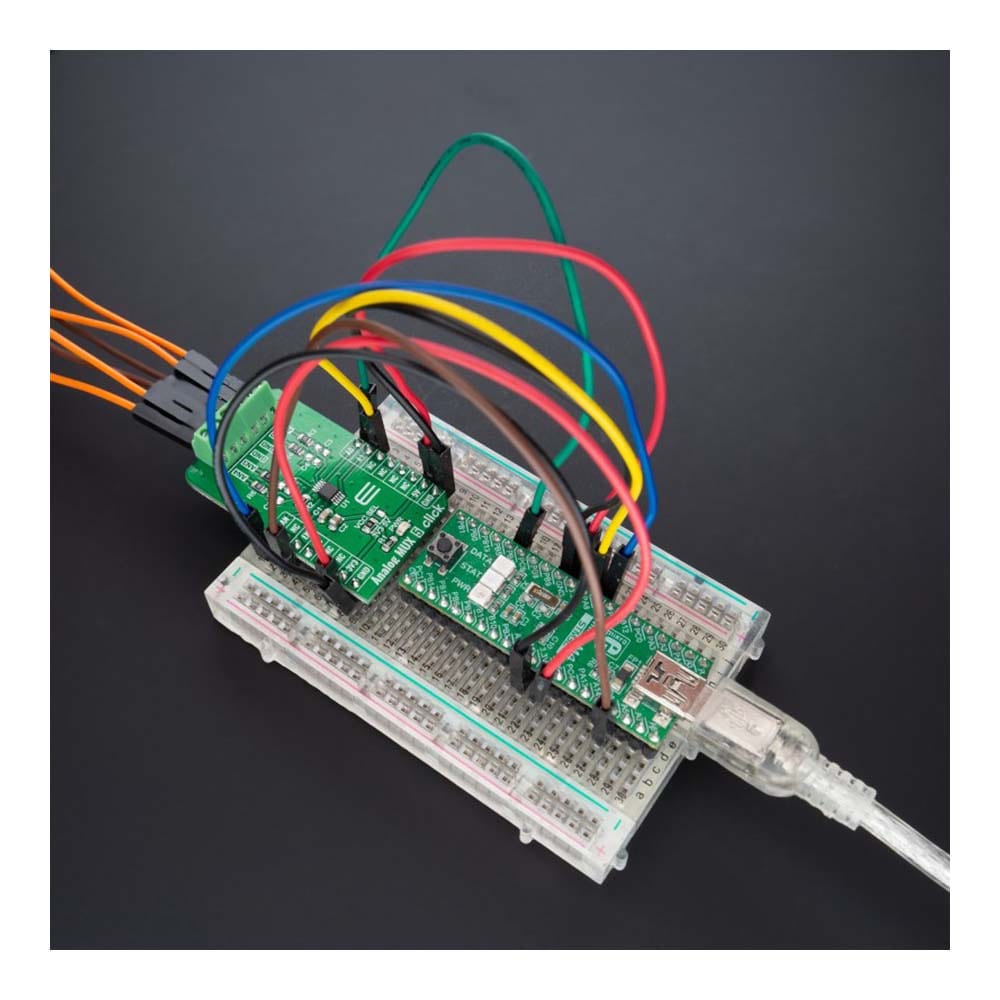
The Analog MUX 5 Click Board™ is a compact add-on board that switches one of many inputs to one output. This board features the MAX4634, a fast, low-voltage four-channel CMOS analog multiplexer from Analog Devices. This low-voltage multiplexer operates from both mikroBUS™ power rails and features 4Ω maximum ON-resistance (RON). CMOS switch construction allows the processing of analog signals within the supply voltage range. It is also characterized by an easy way of management, only through a couple of signals from the mikroBUS™ socket. This Click board™ is suitable for various applications, from industrial and instrumentation to medical, consumer, communications, and more.
The Analog MUX 5 Click Board™ is supported by a mikroSDK compliant library, which includes functions that simplify software development. This Click board™ comes as a fully tested product, ready to be used on a system equipped with the mikroBUS™ socket.
Downloads
Das Analog MUX 5 Click Board™ ist eine kompakte Zusatzplatine, die einen von vielen Eingängen auf einen Ausgang umschaltet. Diese Platine verfügt über den MAX4634, einen schnellen, Niederspannungs-4-Kanal-CMOS-Analogmultiplexer von Analog Devices. Dieser Niederspannungsmultiplexer arbeitet über beide mikroBUS™-Stromschienen und verfügt über einen maximalen Einschaltwiderstand (RON) von 4 Ω. Die CMOS-Schalterkonstruktion ermöglicht die Verarbeitung analoger Signale innerhalb des Versorgungsspannungsbereichs. Es zeichnet sich außerdem durch eine einfache Verwaltung aus, nur durch ein paar Signale von der mikroBUS™-Buchse. Dieses Click Board™ ist für verschiedene Anwendungen geeignet, von Industrie und Instrumentierung bis hin zu Medizin, Verbraucher, Kommunikation und mehr.
Das Analog MUX 5 Click Board™ wird von einer mikroSDK-kompatiblen Bibliothek unterstützt, die Funktionen enthält, die die Softwareentwicklung vereinfachen. Dieses Click Board™ wird als vollständig getestetes Produkt geliefert und ist bereit für den Einsatz auf einem System, das mit der mikroBUS™-Buchse ausgestattet ist.
| General Information | |
|---|---|
Part Number (SKU) |
MIKROE-5120
|
Manufacturer |
|
| Physical and Mechanical | |
Weight |
0.02 kg
|
| Other | |
EAN |
8606027388675
|
Frequently Asked Questions
Have a Question?
Be the first to ask a question about this.