


Mikroelektronika d.o.o.
RTC 16 Click-Platine
RTC 16 Click-Platine
SKU: MIKROE-5083
Verfügbarkeit für Abholungen konnte nicht geladen werden

Key Features
Overview
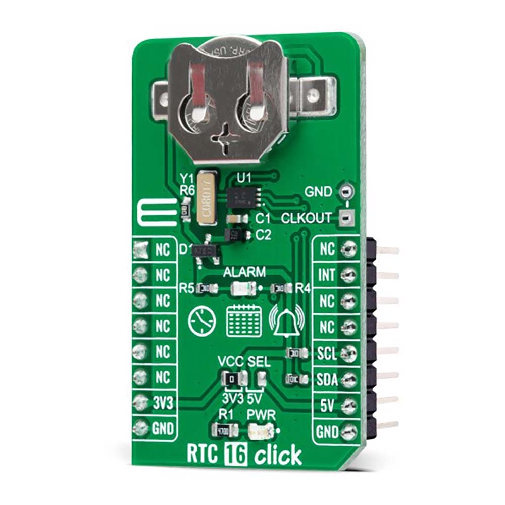
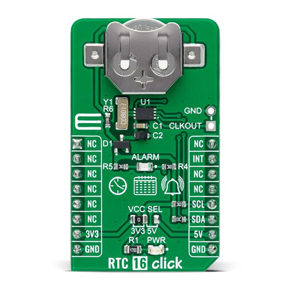
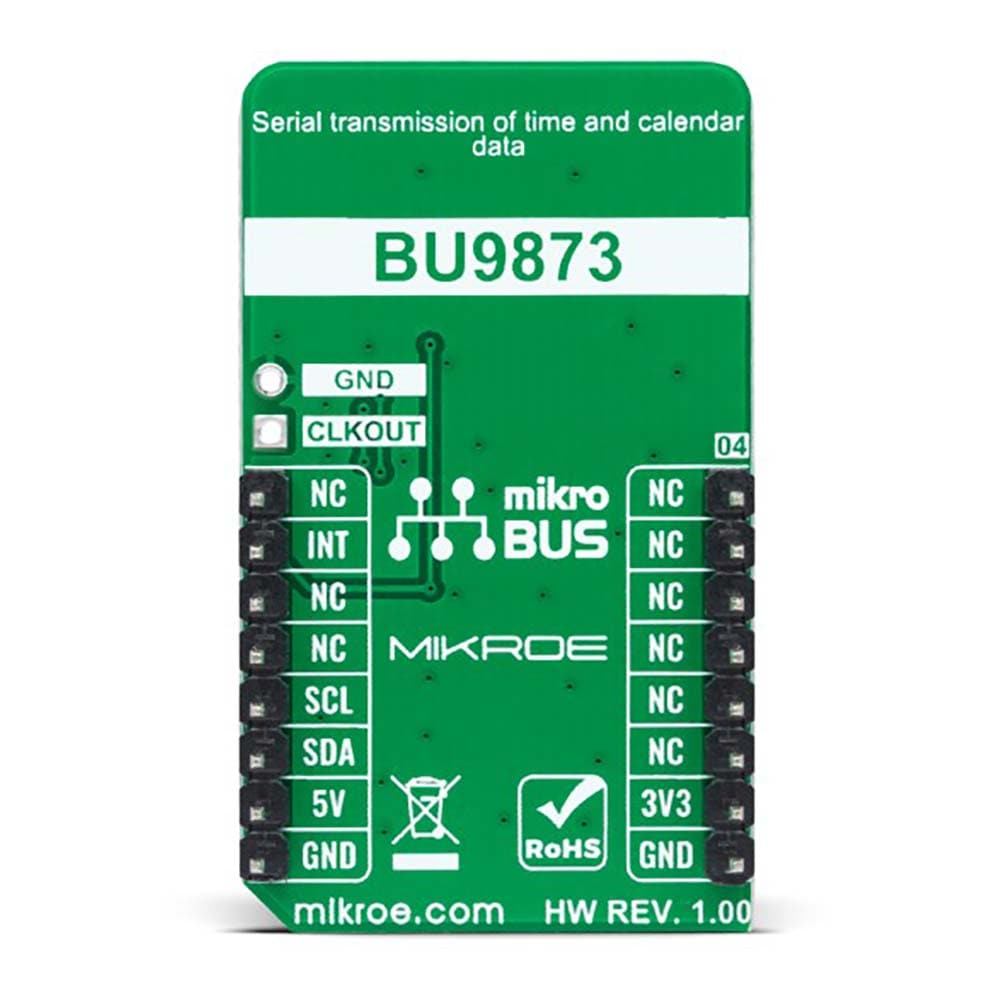
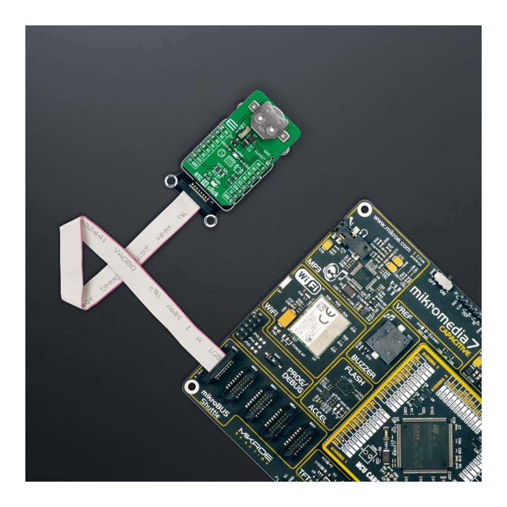
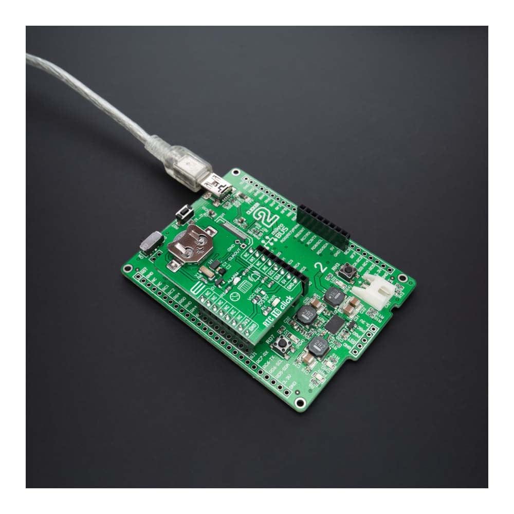
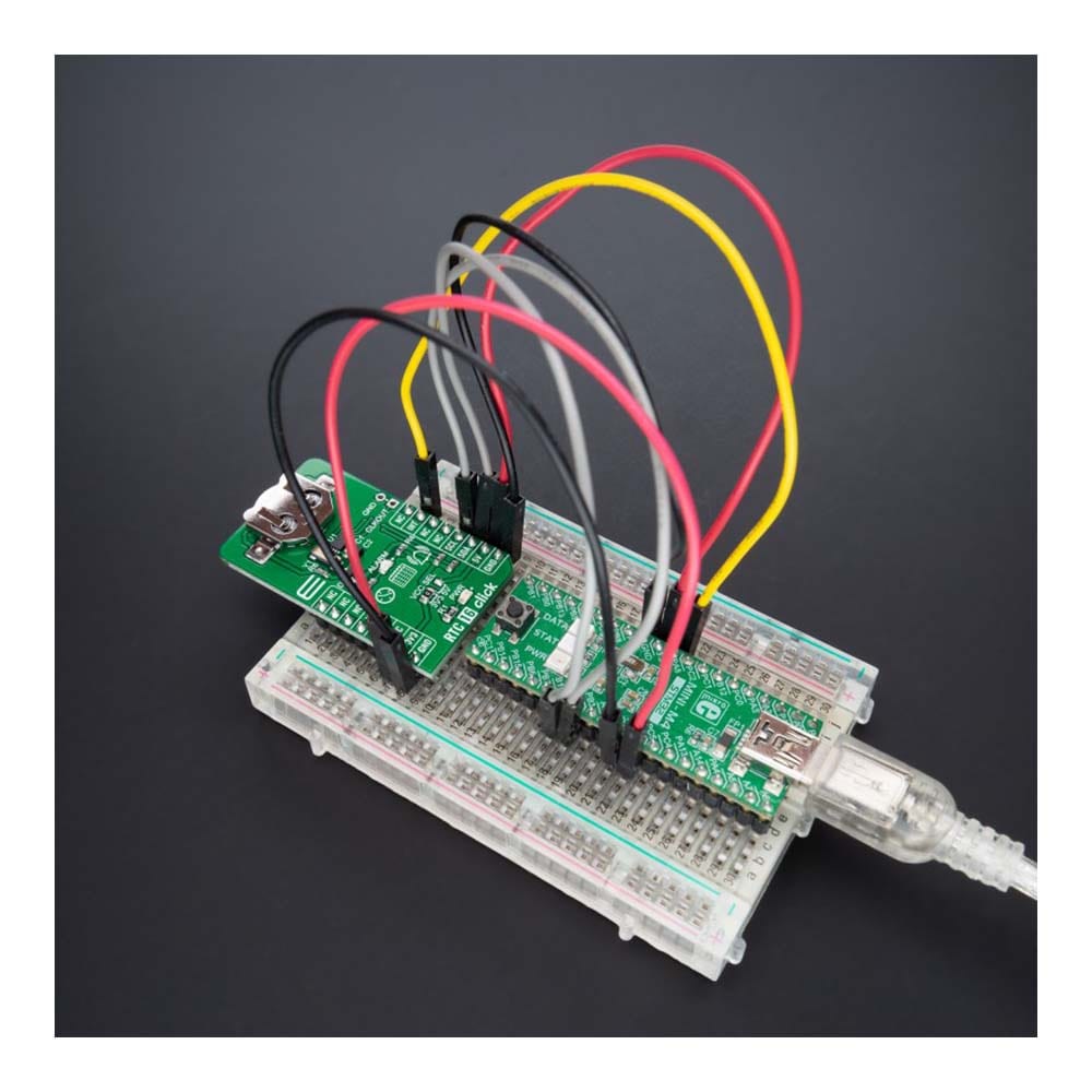
The RTC 16 Click Board™ is a compact add-on board that accurately keeps the time of a day. This board features the BU9873, a CMOS real-time clock with a built-in interrupt generation function from Rohm Semiconductors. The BU9873 provides year, month, day, weekday, hours, minutes, and seconds based on a 32.768kHz quartz crystal. This RTC is connected to the MCU through an I2C interface and configured to serial transmit time and calendar data. It also has an alarm function that outputs an interrupt signal to the MCU when the day of the week, hour, or minute matches the preset time. This Click board™ is suitable for various time-keeping applications, including daily alarms, metering applications, and others requiring an accurate RTC for their operation.
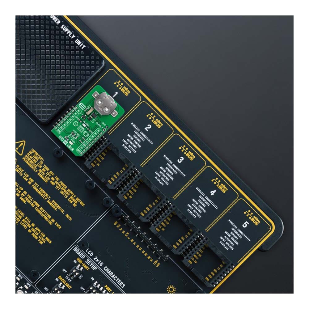
The RTC 16 Click Board™ is supported by a mikroSDK compliant library, which includes functions that simplify software development. This Click board™ comes as a fully tested product, ready to be used on a system equipped with the mikroBUS™ socket.
Downloads
Das RTC 16 Click Board™ ist eine kompakte Zusatzplatine, die die Tageszeit genau angibt. Diese Platine verfügt über die BU9873, eine CMOS-Echtzeituhr mit integrierter Interrupt-Generierungsfunktion von Rohm Semiconductors. Die BU9873 bietet Jahr, Monat, Tag, Wochentag, Stunden, Minuten und Sekunden basierend auf einem 32,768-kHz-Quarzkristall. Diese RTC ist über eine I2C-Schnittstelle mit der MCU verbunden und für die serielle Übertragung von Zeit- und Kalenderdaten konfiguriert. Sie verfügt außerdem über eine Alarmfunktion, die ein Interrupt-Signal an die MCU ausgibt, wenn der Wochentag, die Stunde oder die Minute mit der voreingestellten Zeit übereinstimmt. Diese Click Board™ ist für verschiedene Zeitmessanwendungen geeignet, einschließlich Tagesalarme, Messanwendungen und andere, die für ihren Betrieb eine genaue RTC benötigen.
Das RTC 16 Click Board™ wird von einer mikroSDK-kompatiblen Bibliothek unterstützt, die Funktionen enthält, die die Softwareentwicklung vereinfachen. Dieses Click Board™ wird als vollständig getestetes Produkt geliefert und ist bereit für den Einsatz auf einem System, das mit der mikroBUS™-Buchse ausgestattet ist.
| General Information | |
|---|---|
Part Number (SKU) |
MIKROE-5083
|
Manufacturer |
|
| Physical and Mechanical | |
Weight |
0.02 kg
|
| Other | |
EAN |
8606027389085
|
Frequently Asked Questions
Have a Question?
Be the first to ask a question about this.