


Mikroelektronika d.o.o.
LED-Treiber 14 Click-Platine
LED-Treiber 14 Click-Platine
SKU: MIKROE-4996
Verfügbarkeit für Abholungen konnte nicht geladen werden

Key Features
Overview
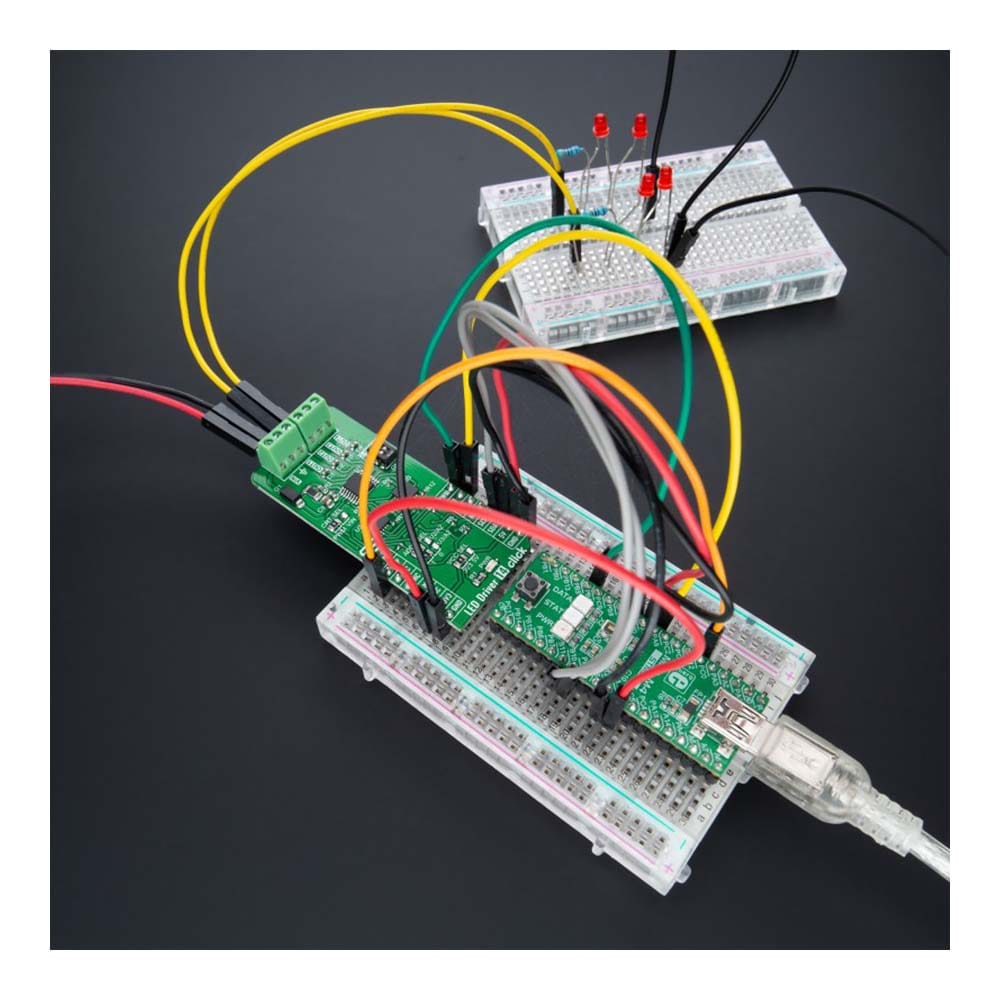
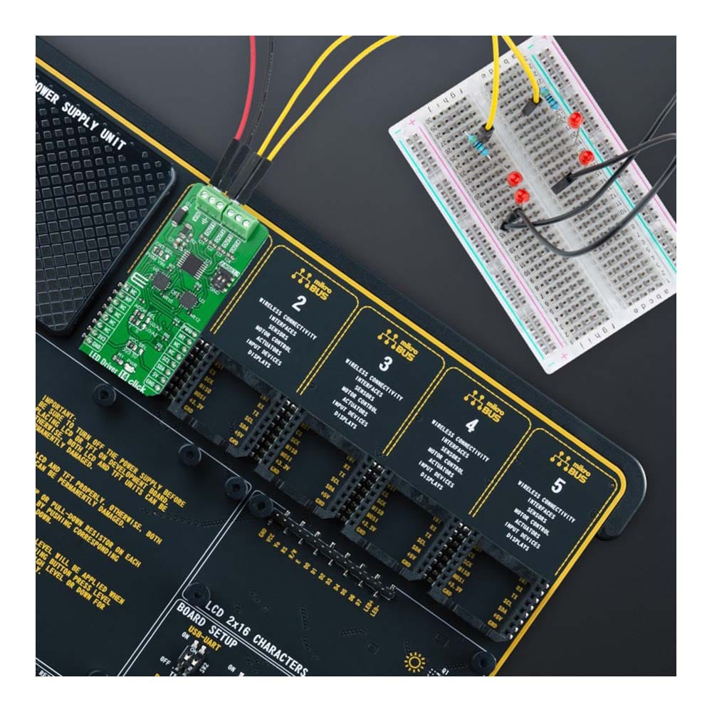
The LED Driver 14 Click Board™ is a compact add-on board that simplifies the control of multiple LEDs. This board features the BD18337EFV-M, a reliable four-channel constant current LED driver from Rohm Semiconductor. It is powered by an external power supply in the range of 5.5V to 20V, providing a maximum output current of 150mA per channel. The BD18337EFV-M also comes with the possibility for up to 3 LEDs in series on its output OUTx pin and built-in energy sharing control, selectable operational mode, and multiple built-in protection functions that protect the circuit during abnormalities. This Click board™ is ideal for LED rear lamps (turn/stop), fog lamps, and turn signals for automotive applications.
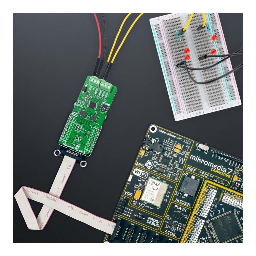
The LED Driver 14 Click Board™ is supported by a mikroSDK compliant library, which includes functions that simplify software development. This Click board™ comes as a fully tested product, ready to be used on a system equipped with the mikroBUS™ socket.
Downloads
Das LED Driver 14 Click Board™ ist eine kompakte Zusatzplatine, die die Steuerung mehrerer LEDs vereinfacht. Diese Platine verfügt über den BD18337EFV-M, einen zuverlässigen Vierkanal-Konstantstrom-LED-Treiber von Rohm Semiconductor. Er wird von einem externen Netzteil im Bereich von 5,5 V bis 20 V versorgt und bietet einen maximalen Ausgangsstrom von 150 mA pro Kanal. Das BD18337EFV-M bietet außerdem die Möglichkeit für bis zu 3 LEDs in Reihe an seinem Ausgangs-OUTx-Pin und eine integrierte Energieteilungssteuerung, einen wählbaren Betriebsmodus und mehrere integrierte Schutzfunktionen, die den Schaltkreis bei Anomalien schützen. Dieses Click Board™ ist ideal für LED-Rückleuchten (Blinker/Bremslicht), Nebelscheinwerfer und Blinker für Automobilanwendungen.
Das LED Driver 14 Click Board™ wird von einer mikroSDK-kompatiblen Bibliothek unterstützt, die Funktionen enthält, die die Softwareentwicklung vereinfachen. Dieses Click Board™ wird als vollständig getestetes Produkt geliefert und ist bereit für den Einsatz auf einem System, das mit der mikroBUS™-Buchse ausgestattet ist.
| General Information | |
|---|---|
Part Number (SKU) |
MIKROE-4996
|
Manufacturer |
|
| Physical and Mechanical | |
Weight |
0.02 kg
|
| Other | |
EAN |
8606027389276
|
Frequently Asked Questions
Have a Question?
Be the first to ask a question about this.