


Mikroelektronika d.o.o.
Ladegerät 18 Click Board
Ladegerät 18 Click Board
SKU: MIKROE-4990
Verfügbarkeit für Abholungen konnte nicht geladen werden

Overview
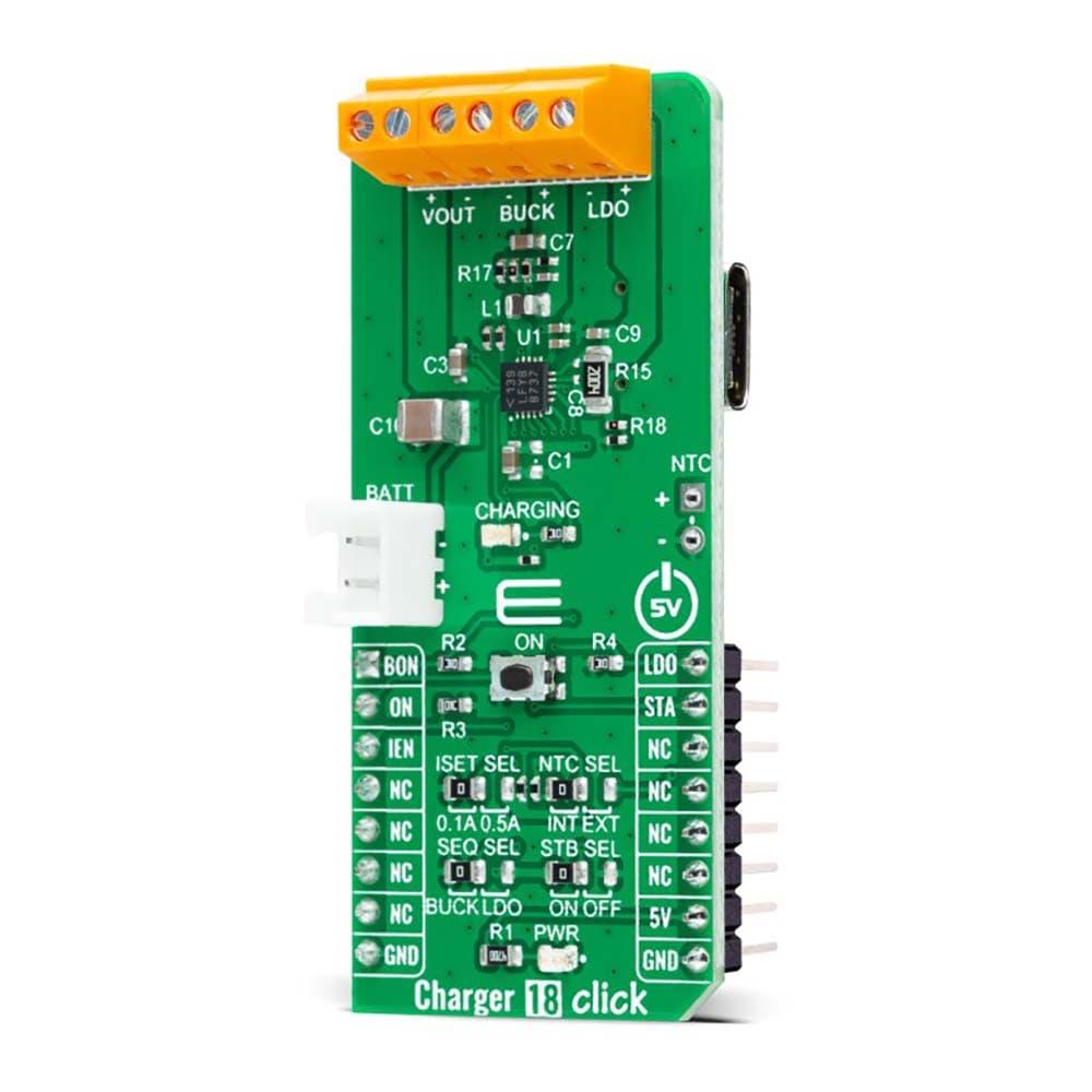
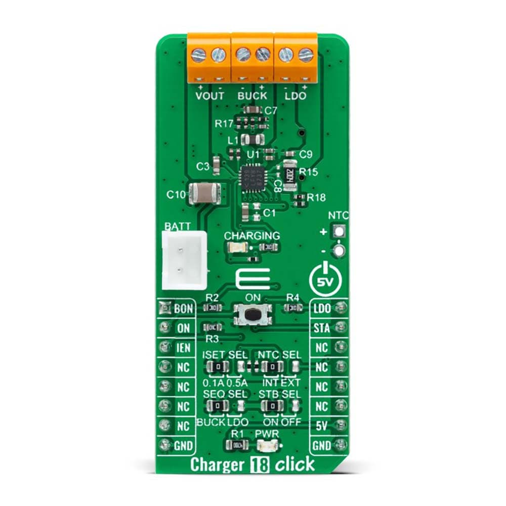
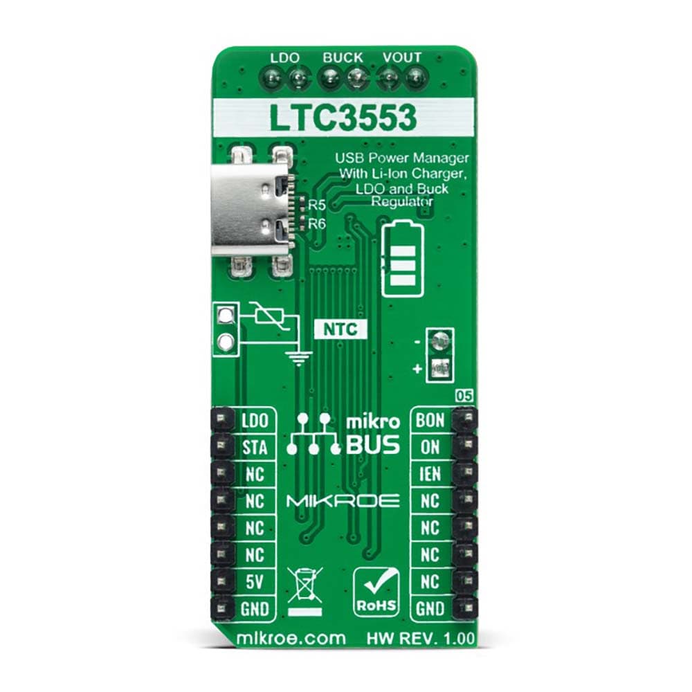
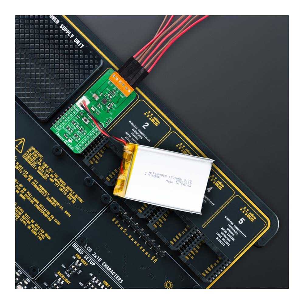
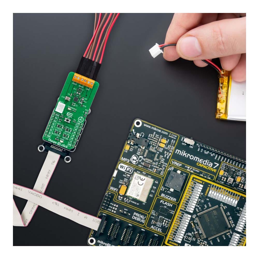
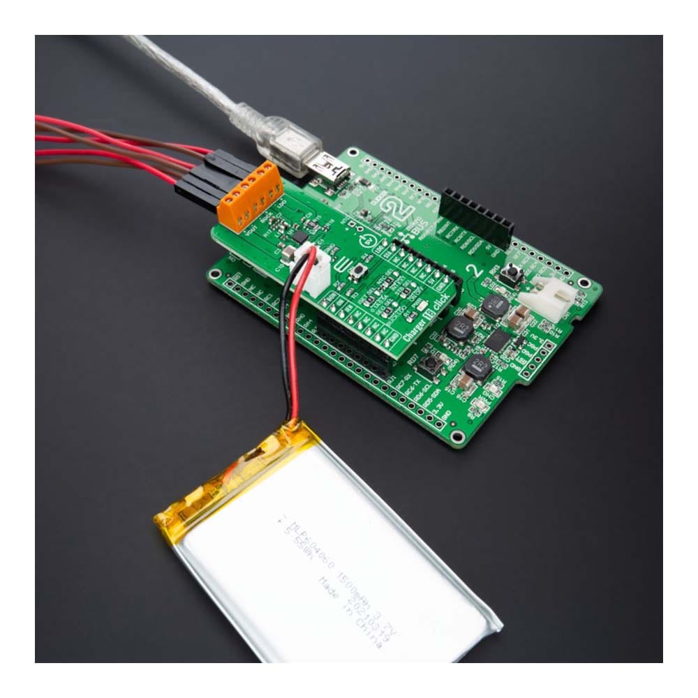
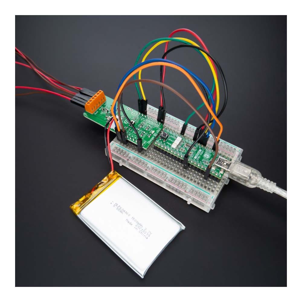
The Charger 18 Click Board™ is a compact add-on board representing a single-cell battery charger. This board features the LTC3553, a micropower, highly integrated power management, and battery charger for single-cell Li-Ion/Polymer battery applications from Analog Devices. Designed specifically for USB applications, it also includes a PowerPath manager with automatic load prioritization and input current limit, a battery charger, and numerous internal protection features. It also indicates a battery charge state, and it comes with a synchronous 200mA buck regulator and a 150mA low dropout linear regulator (LDO). This Click board™ is suitable as a Li-Ion/Polymer battery charger for portable devices and accessories, power tools, and more.
The Charger 18 Click Board™ is supported by a mikroSDK compliant library, which includes functions that simplify software development. This Click board™ comes as a fully tested product, ready to be used on a system equipped with the mikroBUS™ socket.
Downloads
Das Charger 18 Click Board™ ist eine kompakte Zusatzplatine, die ein Einzelzellen-Akkuladegerät darstellt. Diese Platine verfügt über den LTC3553, ein Mikroleistungs-, hochintegriertes Energiemanagement- und Akkuladegerät für Einzelzellen-Li-Ion/Polymer-Akkuanwendungen von Analog Devices. Es wurde speziell für USB-Anwendungen entwickelt und umfasst außerdem einen PowerPath-Manager mit automatischer Lastpriorisierung und Eingangsstrombegrenzung, ein Akkuladegerät und zahlreiche interne Schutzfunktionen. Es zeigt außerdem den Ladezustand des Akkus an und verfügt über einen synchronen 200-mA-Abwärtsregler und einen 150-mA-Low-Dropout-Linearregler (LDO). Dieses Click Board™ eignet sich als Li-Ion/Polymer-Akkuladegerät für tragbare Geräte und Zubehör, Elektrowerkzeuge und mehr.
Das Charger 18 Click Board™ wird von einer mikroSDK-kompatiblen Bibliothek unterstützt, die Funktionen enthält, die die Softwareentwicklung vereinfachen. Dieses Click Board™ wird als vollständig getestetes Produkt geliefert und ist bereit für den Einsatz auf einem System, das mit der mikroBUS™-Buchse ausgestattet ist.
| General Information | |
|---|---|
Part Number (SKU) |
MIKROE-4990
|
Manufacturer |
|
| Physical and Mechanical | |
Weight |
0.02 kg
|
| Other | |
EAN |
8606027389368
|
Frequently Asked Questions
Have a Question?
Be the first to ask a question about this.