


Mikroelektronika d.o.o.
Uhr Gen 6 Click Board
Uhr Gen 6 Click Board
SKU: MIKROE-4973
Verfügbarkeit für Abholungen konnte nicht geladen werden
Key Features
Overview
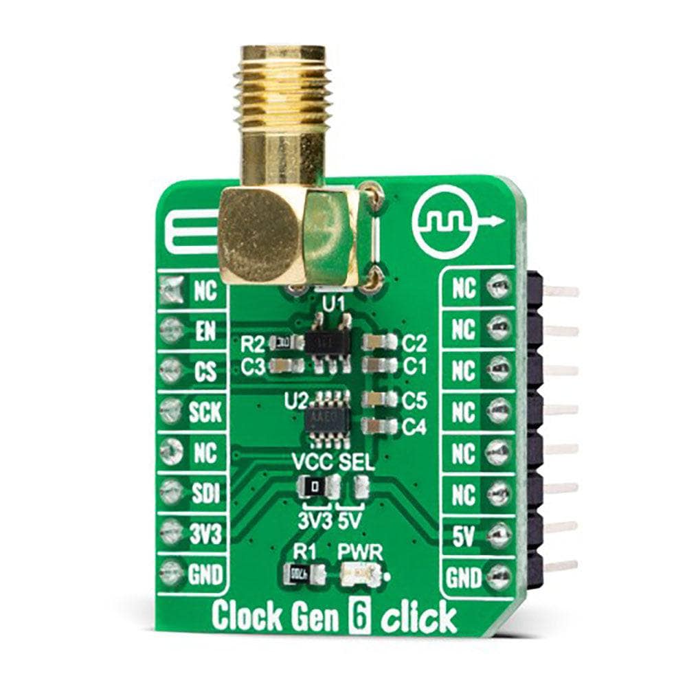
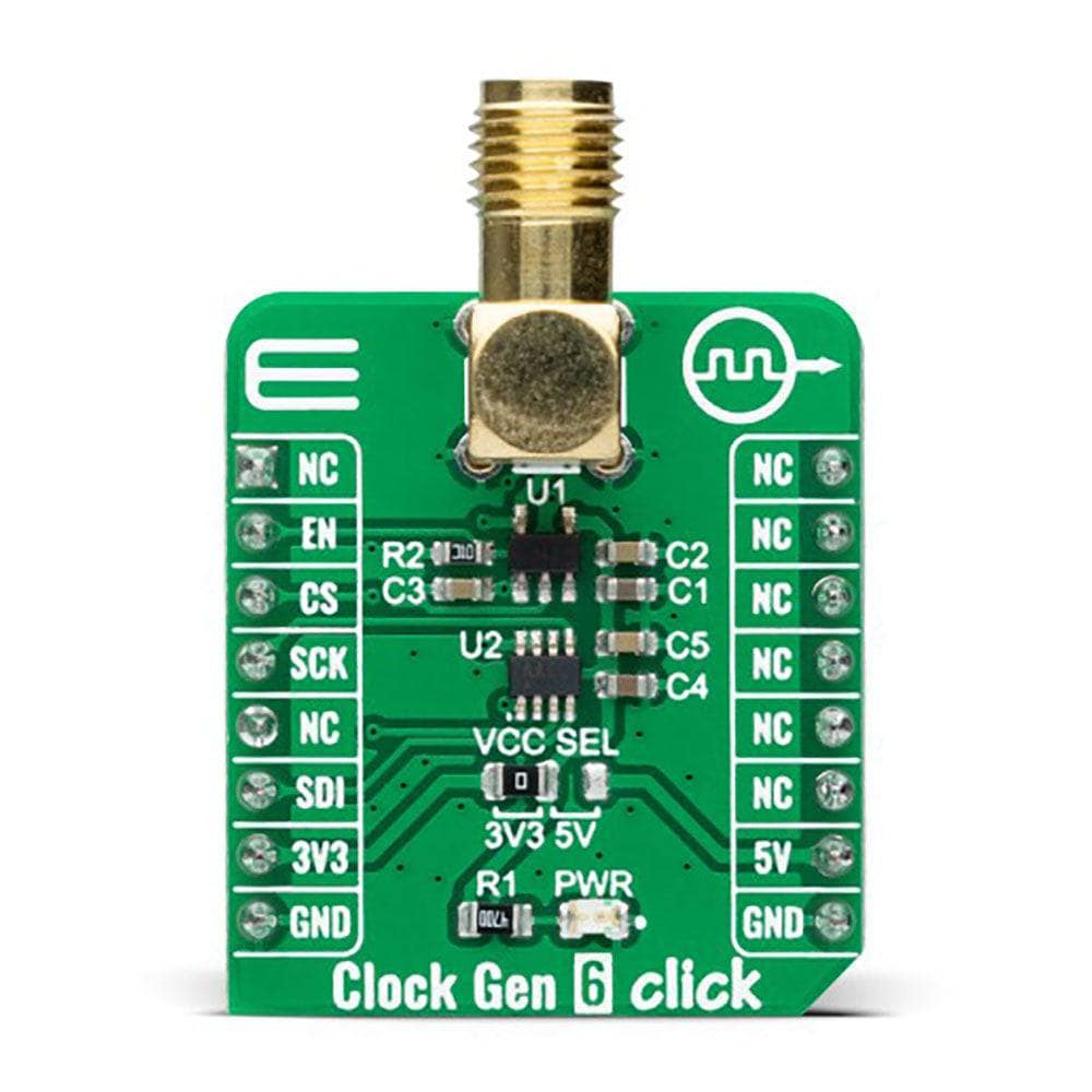
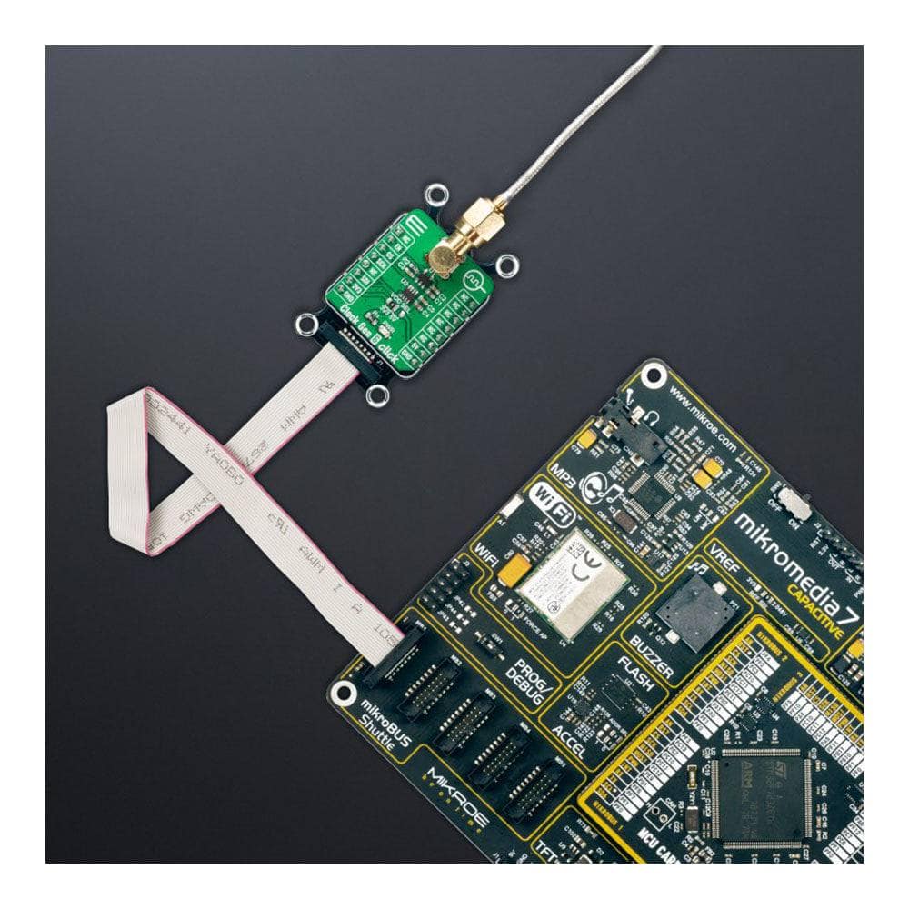
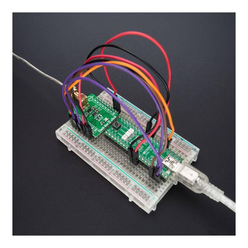
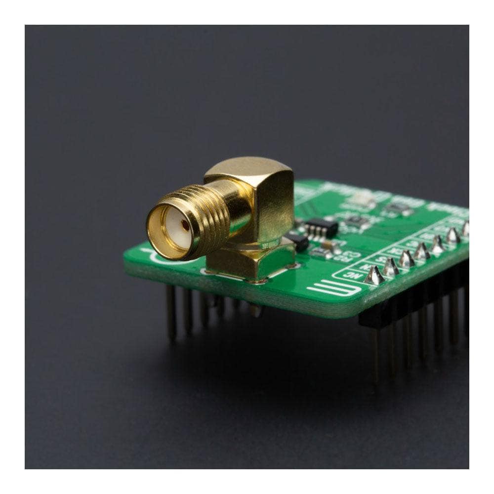
The Clock Gen 6 Click Board™ is a compact add-on board representing a digital oscillator solution. This board features the MIC1557, an IttyBitty CMOS RC oscillator designed to provide rail-to-rail pulses for precise time delay or frequency generation from Microchip Technology. The MIC1557 has a single threshold and trigger connection, internally connected, for astable (oscillator) operation only. It also has an enable/reset control signal routed to the RST pin of the mikroBUS™ socket, which controls the bias supply to the oscillator’s internal circuitry and optimizes power consumption used for oscillator power ON/OFF purposes. In addition, it provides the ability to select the desired frequency programmed via a digital potentiometer, the MAX5401. This Click board™ is suitable for pulse generation, precision timer, time-delay generation, and similar applications.
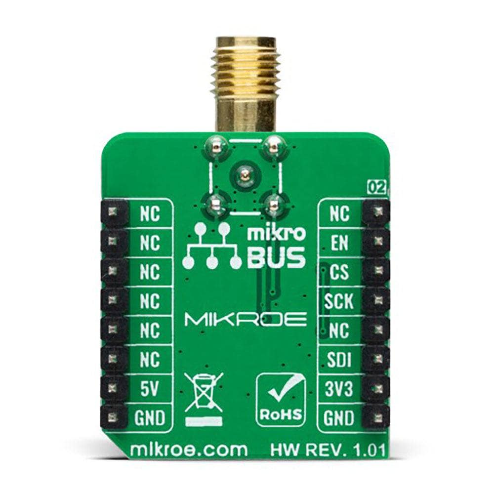
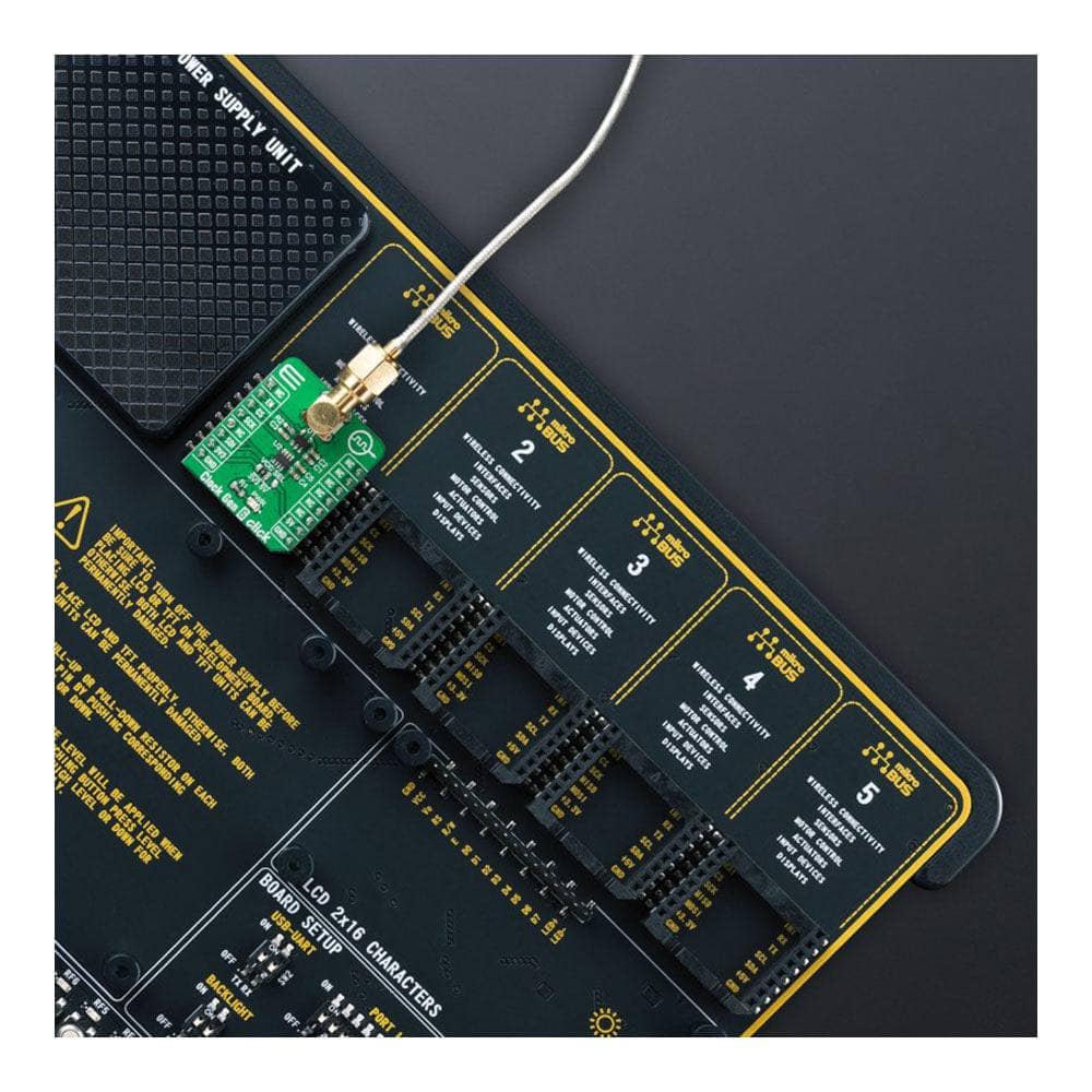
The Clock Gen 6 Click Board™ is supported by a mikroSDK compliant library, which includes functions that simplify software development. This Click board™ comes as a fully tested product, ready to be used on a system equipped with the mikroBUS™ socket.
Downloads
Das Clock Gen 6 Click Board™ ist eine kompakte Zusatzplatine, die eine digitale Oszillatorlösung darstellt. Diese Platine verfügt über den MIC1557, einen IttyBitty CMOS RC-Oszillator, der Rail-to-Rail-Impulse für eine präzise Zeitverzögerung oder Frequenzerzeugung von Microchip Technology liefert. Der MIC1557 verfügt über einen einzelnen Schwellenwert- und Triggeranschluss, der intern verbunden ist, nur für einen astabilen (Oszillator-)Betrieb. Es verfügt außerdem über ein Aktivierungs-/Reset-Steuersignal, das an den RST-Pin der mikroBUS™-Buchse geleitet wird, der die Vorspannungsversorgung der internen Schaltung des Oszillators steuert und den Stromverbrauch für das Ein- und Ausschalten des Oszillators optimiert. Darüber hinaus bietet es die Möglichkeit, die gewünschte Frequenz auszuwählen, die über ein digitales Potentiometer, den MAX5401, programmiert wird. Dieses Click Board™ ist für die Impulserzeugung, Präzisionszeitgeber, Zeitverzögerungserzeugung und ähnliche Anwendungen geeignet.
Das Clock Gen 6 Click Board™ wird von einer mikroSDK-kompatiblen Bibliothek unterstützt, die Funktionen enthält, die die Softwareentwicklung vereinfachen. Dieses Click Board™ wird als vollständig getestetes Produkt geliefert und ist bereit für den Einsatz auf einem System, das mit der mikroBUS™-Buchse ausgestattet ist.
| General Information | |
|---|---|
Part Number (SKU) |
MIKROE-4973
|
Manufacturer |
|
| Physical and Mechanical | |
Weight |
0.02 kg
|
| Other | |
EAN |
8606027388132
|
Frequently Asked Questions
Have a Question?
Be the first to ask a question about this.