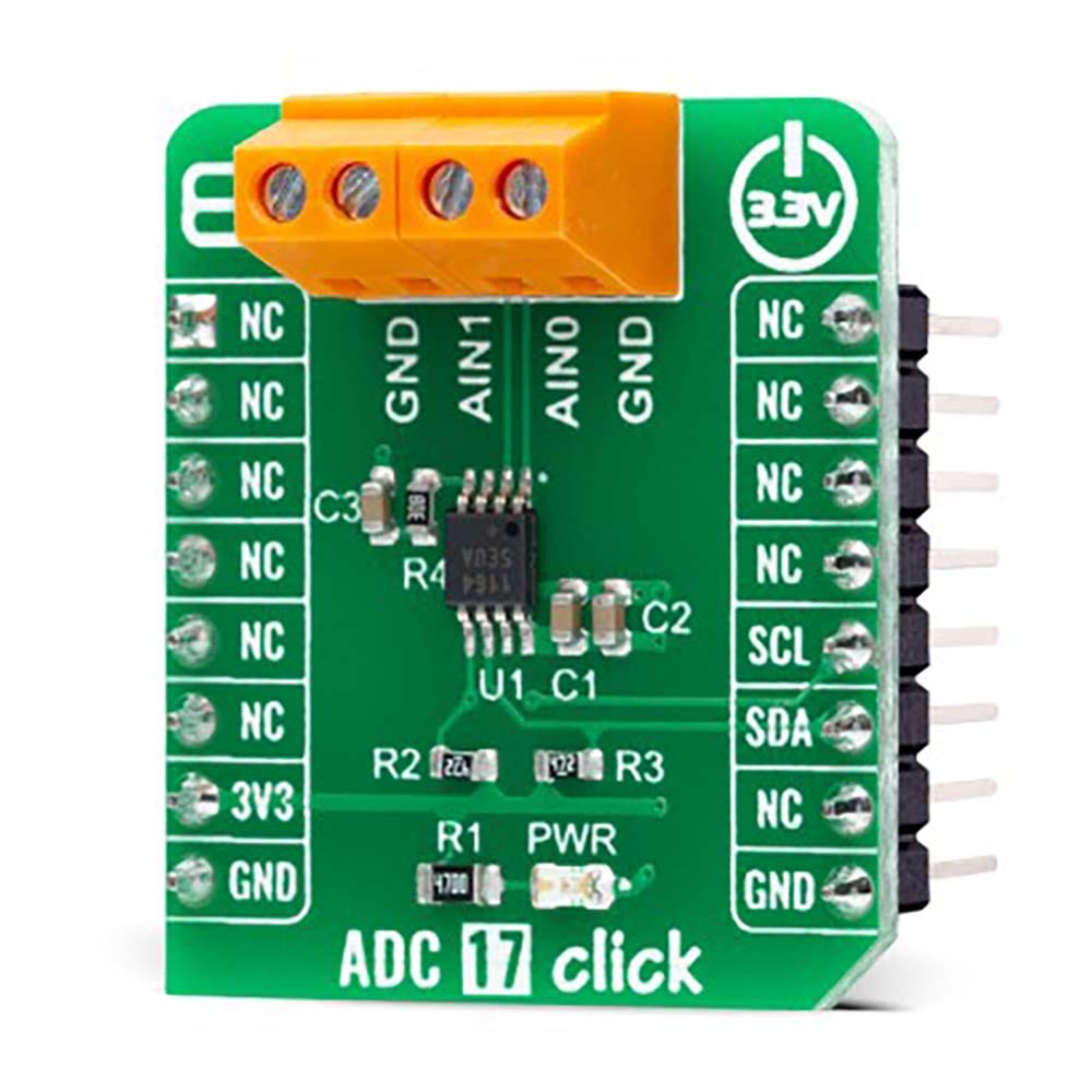
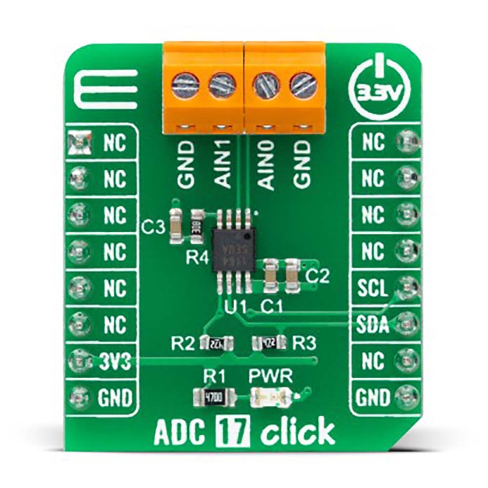
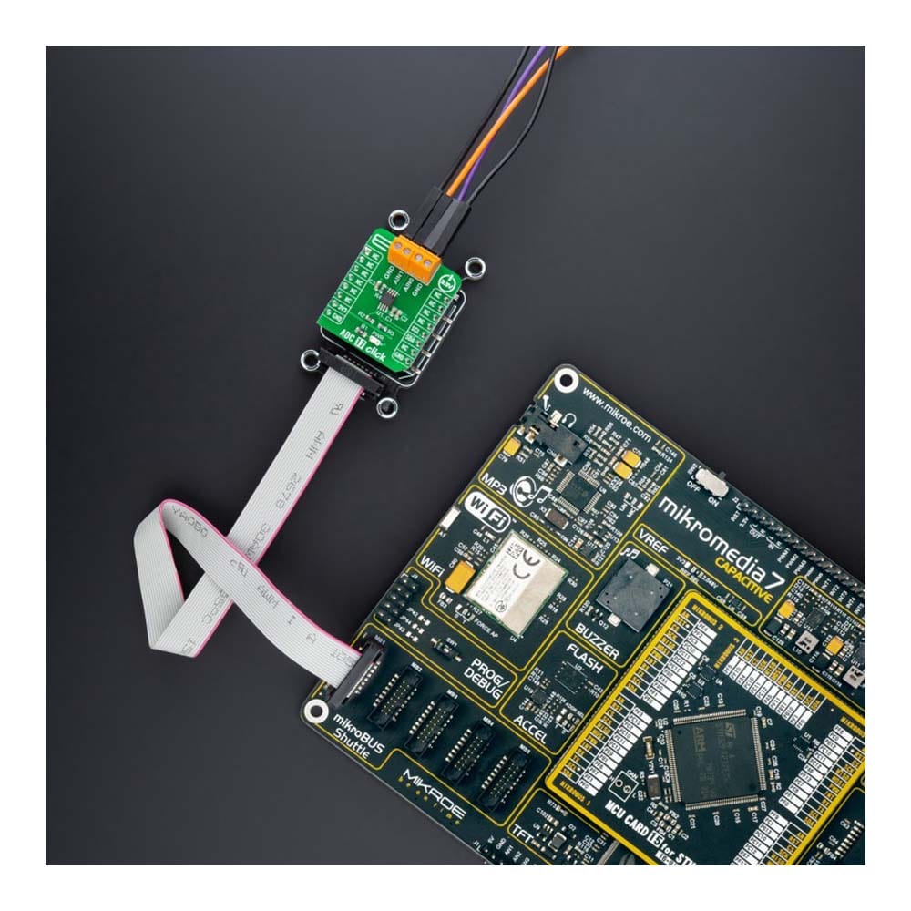
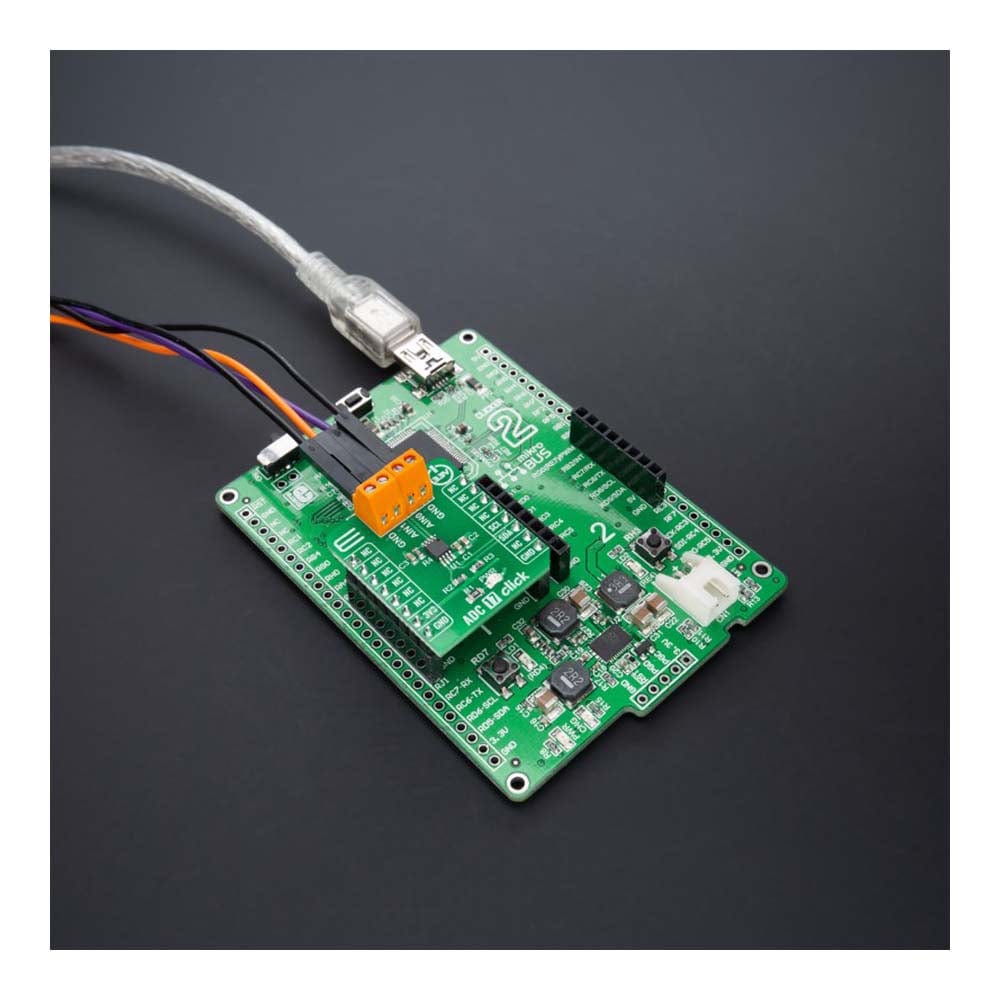
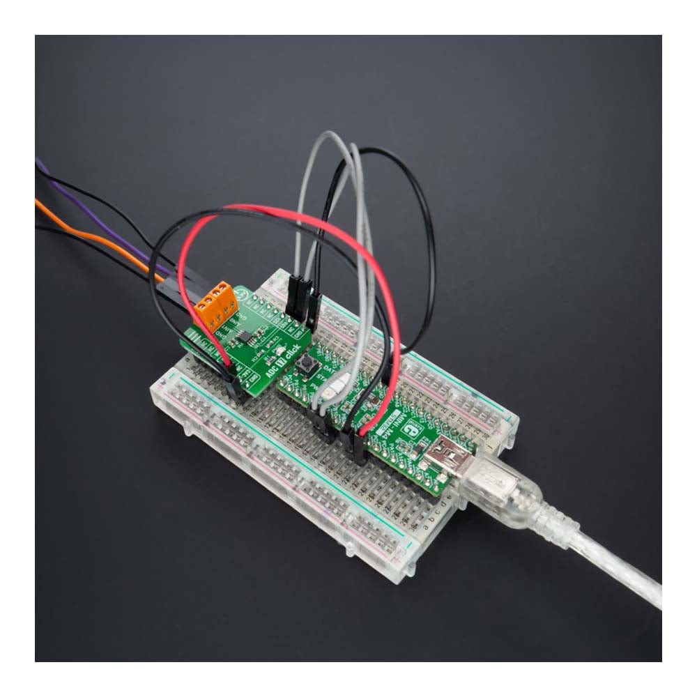
ADC 17 Click-Platine
Key Features
- Zwei Single-Ended-Kanäle oder ein volldifferenzieller Kanal, geringer Stromverbrauch, hohe Genauigkeit, softwarekonfigurierbarer unipolarer/bipolarer Betrieb, interne 2,048-V-Referenz, Hochgeschwindigkeits-I2C-Schnittstelle und mehr
- Basierend auf dem MAX11645 – leistungsstarker Zweikanal-Analog-Digital-Wandler (ADC) von Analog Devices
- Kann für verschiedene Anwendungen verwendet werden, von Energiegewinnungssensoren bis hin zu tragbarer Unterhaltungselektronik, Lastpunktüberwachung (Spannung, Strom und Temperatur) und mehr
- mikroBUS: I2C-Schnittstelle
Das ADC 17 Click Board™ ist eine kompakte Zusatzplatine, die einen Hochleistungsdatenkonverter enthält. Diese Platine verfügt über den MAX11645, einen stromsparenden 12-Bit-Analog-Digital-Konverter mit zwei Kanälen von Analog Devices. Der MAX11645 misst zwei unsymmetrische oder einen Differenzeingang. Die vollständig differenziellen Analogeingänge sind per Software konfigurierbar (I2C-Schnittstelle) für unipolaren oder bipolaren sowie unsymmetrischen oder differenziellen Betrieb. Die interne Referenz von 2,048 V bestimmt den analogen Eingangsbereich in vollem Maßstab. Dieses Click Board™ bietet vollständige, hochpräzise Lösungen für die anspruchsvollsten Anwendungen von Energiegewinnungssensoren bis hin zu tragbarer Unterhaltungselektronik, Lastpunktüberwachung (Spannung, Strom und Temperatur) und mehr.
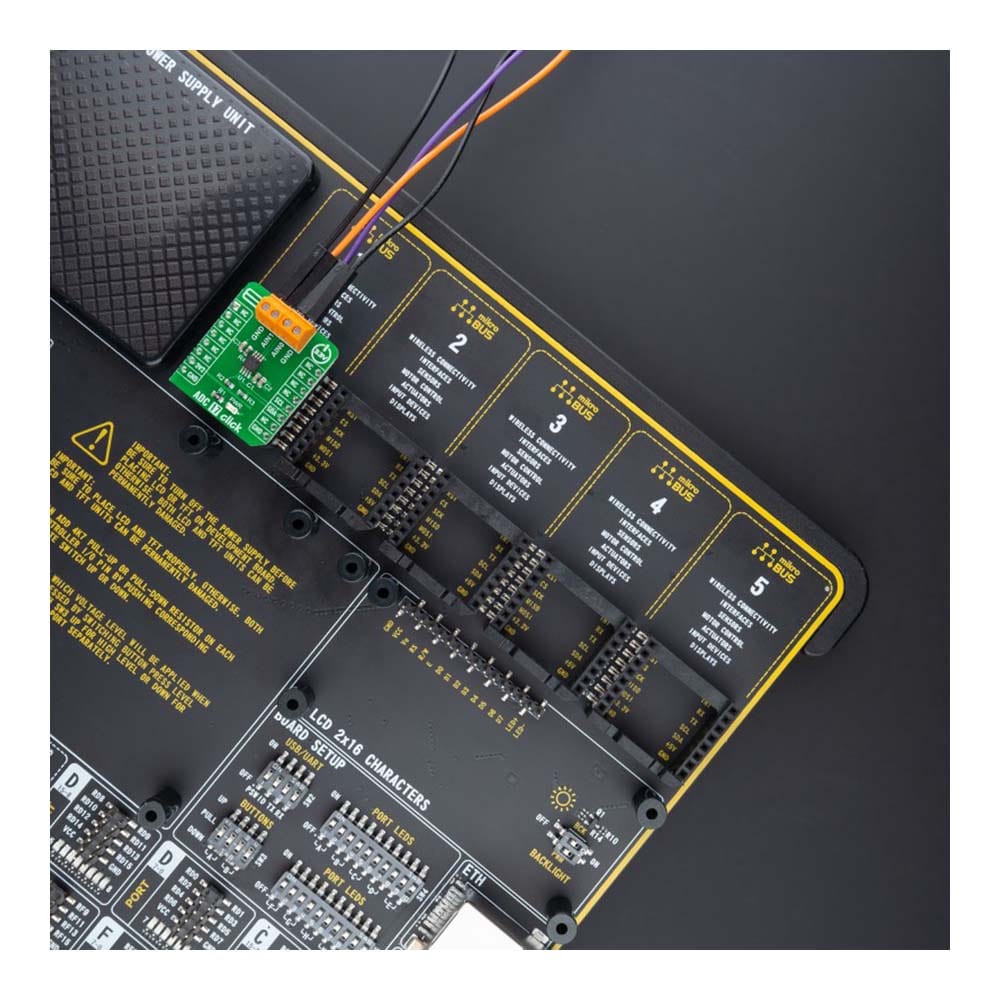
Das ADC 17 Click Board™ wird von einer mikroSDK-kompatiblen Bibliothek unterstützt, die Funktionen enthält, die die Softwareentwicklung vereinfachen. Dieses Click Board™ wird als vollständig getestetes Produkt geliefert und ist bereit für den Einsatz auf einem System, das mit der mikroBUS™-Buchse ausgestattet ist.
How Does The ADC 17 Click Board™ Work?
The ADC 17 Click Board™ as its foundation uses the MAX11645, a high-performance two-channel analog-to-digital converter (ADC) from Analog Devices. The MAX11645 uses successive-approximation conversion technique and fully differential input track/hold (T/H) circuitry to capture and convert an analog signal to a serial 12-bit digital output. It can measure either two single-ended or one differential input(s).
The MAX11645 is capable of sample rates up to 94ksps. By taking advantage of the ADC's high sample rate, multiple channels can be converted in a short period. This capability allows the device to spend more time in shutdown mode, reducing total power consumption. It also includes a 2.048V internal reference which determines its full-scale analog input range. The fully differential analog inputs are software configurable for unipolar or bipolar applications; input signals from 0 to VREF (unipolar) or ±VREF/2 (bipolar) range can be resolved with accurate 12-bit accuracy.
The ADC 17 Click Board™ communicates with MCU using the standard I2C 2-Wire interface to read data and configure settings, supporting Standard Mode operation with a clock frequency of 100kHz and Fast Mode up to 400kHz.
The ADC 17 Click Board™can be operated only with a 3.3V logic voltage level. The board must perform appropriate logic voltage level conversion before using MCUs with different logic levels. However, the Click board™ comes equipped with a library containing functions and an example code that can be used, as a reference, for further development.
SPECIFICATIONS
Type | ADC |
Applications | The ADC 17 Click Board™ be used for various applications from energy-harvesting sensors to portable consumer electronics, point-of-load monitoring (voltage, current, and temperature), and more |
On-board modules | MAX11645 - high-performance two-channel analog-to-digital converter (ADC) from Analog Devices |
Key Features | Two single-ended channels or one fully differential channel, low power consumption, high accuracy, software-configurable unipolar/bipolar operation, internal 2.048V reference, high-speed I2C interface, and more |
Interface | I2C |
Compatibility | mikroBUS |
Click board size | S (28.6 x 25.4 mm) |
Input Voltage | 3.3V |
PINOUT DIAGRAM
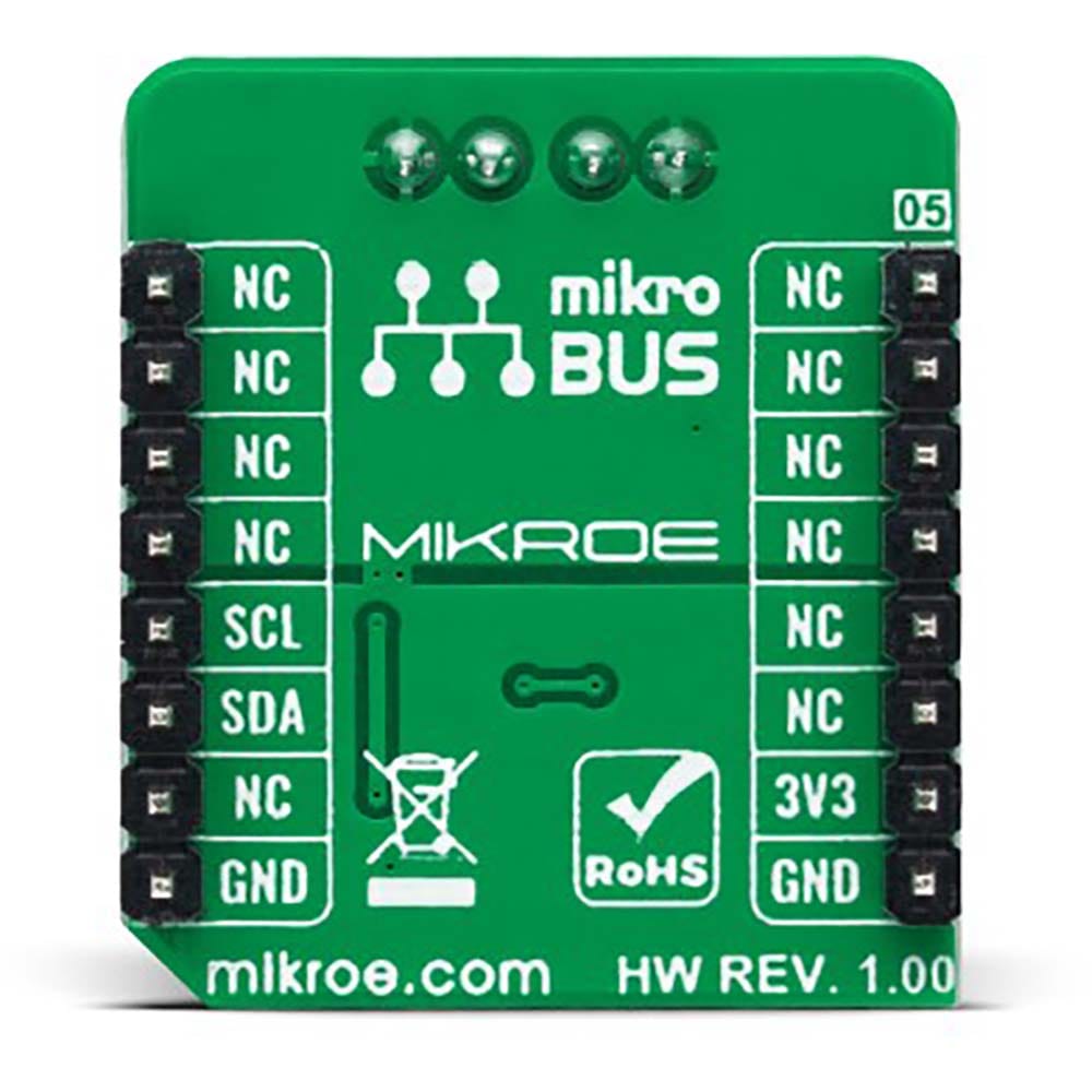
This table shows how the pinout of the ADC 17 Click Board™ corresponds to the pinout on the mikroBUS™ socket (the latter shown in the two middle columns).
Notes | Pin | Pin | Notes | ||||
---|---|---|---|---|---|---|---|
NC | 1 | AN | PWM | 16 | NC | ||
NC | 2 | RST | INT | 15 | NC | ||
NC | 3 | CS | RX | 14 | NC | ||
NC | 4 | SCK | TX | 13 | NC | ||
NC | 5 | MISO | SCL | 12 | SCL | I2C Clock | |
NC | 6 | MOSI | SDA | 11 | SDA | I2C Data | |
Power Supply | 3.3V | 7 | 3.3V | 5V | 10 | NC | |
Ground | GND | 8 | GND | GND | 9 | GND | Ground |
ONBOARD SETTINGS AND INDICATORS
Label | Name | Default | Description |
---|---|---|---|
LD1 | PWR | - | Power LED Indicator |
ADC 17 CLICK ELECTRICAL SPECIFICATIONS
Description | Min | Typ | Max | Unit |
---|---|---|---|---|
Supply Voltage | - | 3.3 | - | V |
Analog Input Voltage | 0 | - | 2.048 | V |
Resolution | - | 12 | - | bits |
Operating Temperature Range | -40 | +25 | +30 | °C |
Software Support
We provide a library for the ADC 17 Click Board™ as well as a demo application (example), developed using MikroElektronika compilers. The demo can run on all the main MikroElektronika development boards.
The package can be downloaded/installed directly from NECTO Studio The package Manager (recommended), downloaded from our LibStock™ or found on MikroE Github account.
Library Description
This library contains API for the ADC 17 Click Board™ driver.
Key functions
-
adc17_set_channel
This function sets the selected channel active by modifying the config byte. -
adc17_get_voltage
This function reads the voltage from the previously selected channel by using I2C serial interface. -
adc17_write_setup_byte
This function writes a setup byte to the ADC chip by using I2C serial interface.
Example Description
This example demonstrates the use of the ADC 17 Click Board™ by reading the voltage from the two analog input channels.
void application_task ( void )
{
float voltage;
if ( ADC17_OK == adc17_set_channel ( &adc17, ADC17_CHANNEL_0 ) )
{
if ( ADC17_OK == adc17_get_voltage ( &adc17, &voltage ) )
{
log_printf ( &logger, " AIN0 voltage: %.3f V rnn", voltage );
}
}
if ( ADC17_OK == adc17_set_channel ( &adc17, ADC17_CHANNEL_1 ) )
{
if ( ADC17_OK == adc17_get_voltage ( &adc17, &voltage ) )
{
log_printf ( &logger, " AIN1 voltage: %.3f V rnn", voltage );
}
}
Delay_ms ( 500 );
}
The full application code, and ready to use projects can be installed directly from NECTO Studio The package Manager (recommended), downloaded from our LibStock™ or found on MikroE Github account.
Other MikroE Libraries used in the example:
- MikroSDK.Board
- MikroSDK.Log
- Click.ADC17
Additional Notes and Information
Depending on the development board you are using, you may need USB UART click, USB UART 2 Click or RS232 Click to connect to your PC, for development systems with no UART to USB interface available on the board. UART terminal is available in all MikroElektronika compilers.
MIKROSDK
The ADC 17 Click Board™ is supported with mikroSDK - MikroElektronika Software Development Kit. To ensure proper operation of mikroSDK compliant Click board™ demo applications, mikroSDK should be downloaded from the LibStock and installed for the compiler you are using.
ADC 17 Click-Platine
Frequently Asked Questions
Have a Question?
Be the first to ask a question about this.