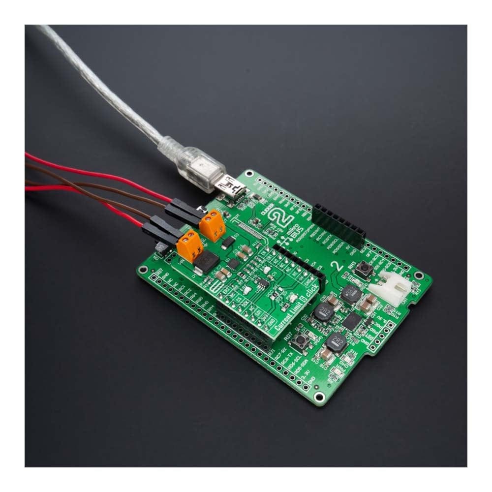
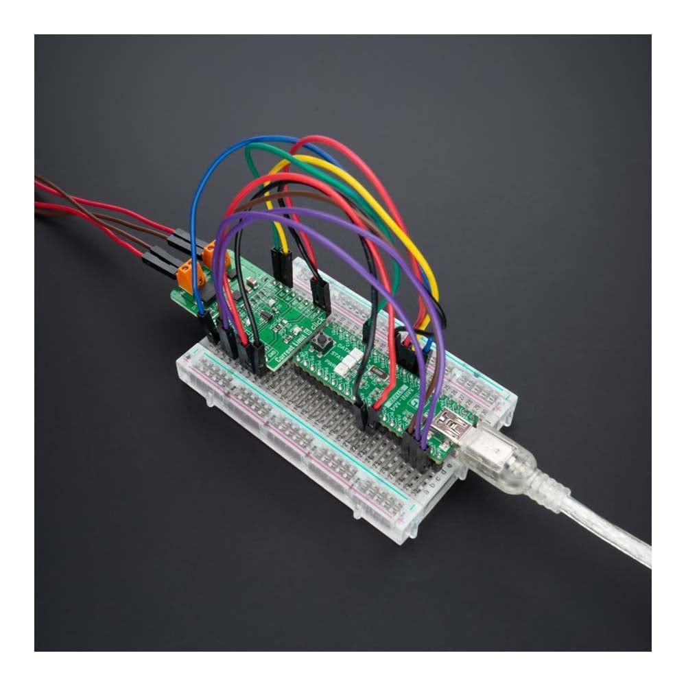
Strombegrenzung 6 Click Board
Overview
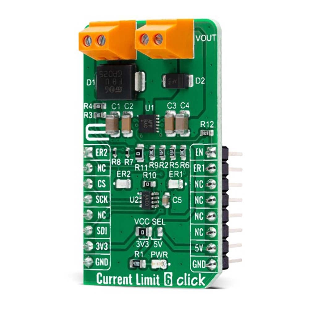
Das Current Limit 6 Click Board™ ist eine kompakte Zusatzplatine, die eine Strombegrenzungslösung darstellt. Diese Platine verfügt über das einstellbare Überspannungs- und Überstromschutzgerät MAX17608 von Maxim Integrated, jetzt Teil von Analog Devices. Dieses Click Board™ ist ideal zum Schutz von Systemen mit dem flexiblen Eingangsüberspannungsschutzbereich von 4,5 V bis 60 V und dem einstellbaren Eingangsunterspannungsschutzbereich von 4,5 V bis 59 V. Außerdem beträgt die maximale Strombegrenzung 1 A und kann über ein digitales Potentiometer MAX5401 programmiert werden. Wenn der Gerätestrom den programmierten Schwellenwert erreicht, verhindert das Gerät weitere Stromanstiege durch Modulation des FET-Widerstands.
Das Current Limit 6 Click Board™ eignet sich für Anwendungen in tragbaren Geräten, Prozessinstrumenten und zur Zustandsüberwachung oder mit Stromversorgungen und schützt diese bei Kurzschlüssen oder anderen Überlastbedingungen.
How Does The Current Limit 6 Click Board™ Work?
The Current Limit 6 Click Board™ as its foundation uses the MAX17608, a current-limiting device with an adjustable overvoltage and overcurrent protection feature from Maxim Integrated, now part of Analog Devices. The MAX17608 offers flexible protection boundaries for systems against input voltage ranging from 4.5V to 60V and limits the output load current to a programmed level (up to 1A). The devices also feature two internal MOSFETs connected in series, with a low cumulative RON of 260mΩ typical. Input undervoltage protection can be programmed between 4.5V and 59V, while the overvoltage protection can be independently programmed between 5.5V and 60V (default Click board™ configuration is 4.5V for UVLO and 14V for OVLO). Additionally, the MAX17608 has an internal default undervoltage lockout set at 4V typical.
The current-limit switch is virtually ubiquitous in system control and provides a safe means for regulating the current delivered to a load circuit. It allows the load current to increase to a programmed limit but no higher. Typically, the current limit is a function of the voltage across an external resistor, and this voltage serves as the reference for an internal current-limiting amplifier. By replacing the resistor with a digital potentiometer, you can easily program the current limit as performed on this Click board™. For this purpose, the digital potentiometer MAX5401 from Maxim Integrated, which communicates with the MCU via 3-Wire SPI serial interface, is used to set the resistance on the MAX17608 SETI pin, adjusting the current limit for the switch between 0.1A to 1 A.
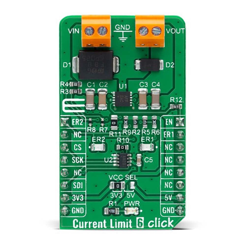
This current limiter offers several operational modes, selectable through a populated jumper labelled as R11 connected to the CLMD pin of the MAX17608. In a default configuration, this pin is connected to the ground, representing the Continuous mode of operation. When R11 is replaced with a 150kΩ resistor, this Click board™ is in the Latch-off mode, and when the user leaves this pin unconnected Autoretry mode of operation is activated. More information on the operational modes can be found in the attached datasheet.
The Current Limit 6 Click Board™ can be enabled or disabled through the EN pin routed to the PWM pin of the mikroBUS™ socket; hence, offering a switch operation to turn ON/OFF power delivery to the connected load. It also provides communication signals routed to the INT and AN pins of the mikroBUS™ socket, alongside its LED indicators labelled as ER1 and ER2, to indicate different operational and fault signals such as FLAG and UVOV signals. Besides, the MAX17608 also offers internal thermal shutdown protection against excessive power dissipation.
The Current Limit 6 Click Board™ can operate with both 3.3V and 5V logic voltage levels selected via the VCC SEL jumper. This way, it is allowed for both 3.3V and 5V capable MCUs to use the communication lines properly. However, the Click board™ comes equipped with a library containing easy-to-use functions and an example code that can be used, as a reference, for further development.
SPECIFICATIONS
Type | Power Switch |
Applications | The Current Limit 6 Click Board™ be used for applications in portable equipment, process instrumentation, and condition monitoring, or with power supplies, protecting them in a short circuit or other overload conditions |
On-board modules | MAX17608 - current-limiting device with an adjustable overvoltage and overcurrent protection feature from Maxim Integrated, now part of Analog Devices |
Key Features | OVLO/UVLO and reverse voltage protection, programmable current limiting up to 1A, wide input-supply range up to 60V, thermal overload protection, operational and fault signals indicators, and more |
Interface | GPIO,SPI |
Compatibility | mikroBUS |
Click board size | M (42.9 x 25.4 mm) |
Input Voltage | 3.3V or 5V,External |
PINOUT DIAGRAM
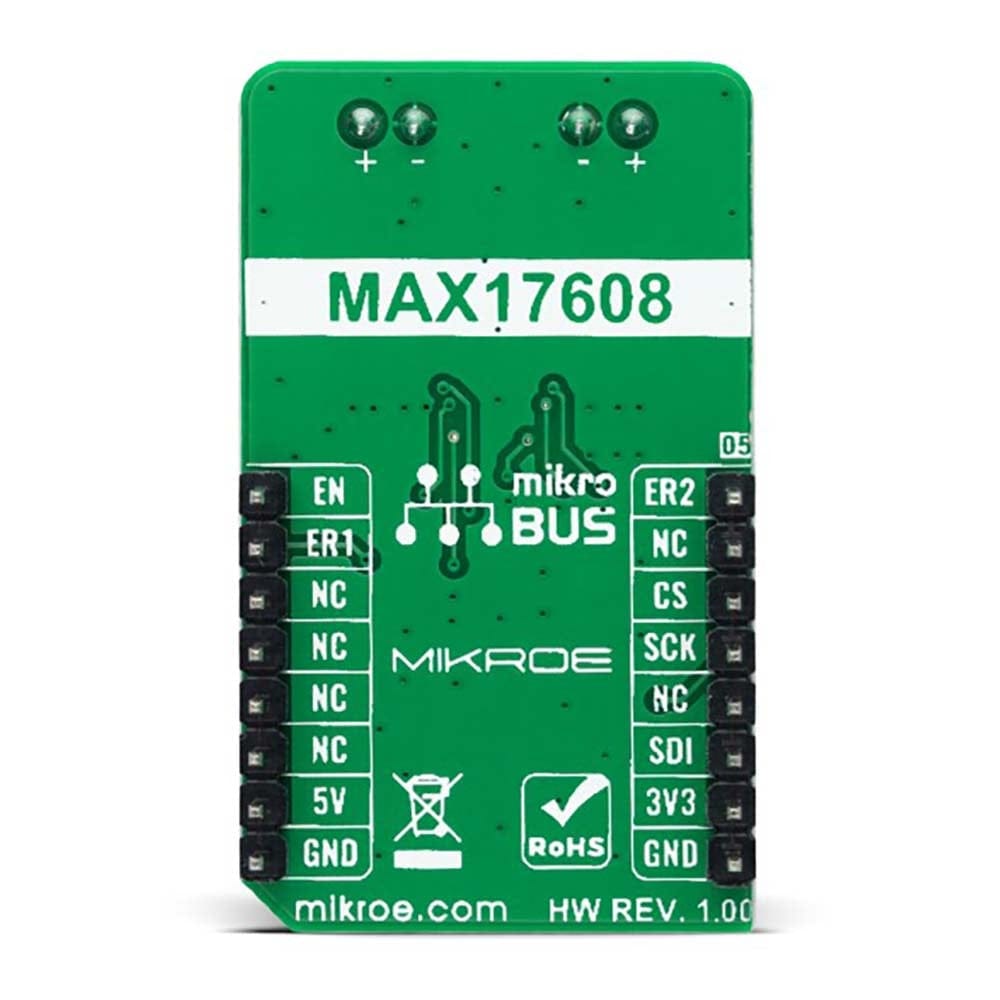
This table shows how the pinout for the Current Limit 6 Click Board™ corresponds to the pinout on the mikroBUS™ socket (the latter shown in the two middle columns).
Notes | Pin | Pin | Notes | ||||
---|---|---|---|---|---|---|---|
UVLO/OVLO Indicator | ER2 | 1 | AN | PWM | 16 | EN | Enable |
NC | 2 | RST | INT | 15 | ER1 | Fault Indicator | |
SPI Chip Select | CS | 3 | CS | RX | 14 | NC | |
SPI Clock | SCK | 4 | SCK | TX | 13 | NC | |
NC | 5 | MISO | SCL | 12 | NC | ||
SPI Data IN | SDI | 6 | MOSI | SDA | 11 | NC | |
Power Supply | 3.3V | 7 | 3.3V | 5V | 10 | 5V | Power Supply |
Ground | GND | 8 | GND | GND | 9 | GND | Ground |
ONBOARD SETTINGS AND INDICATORS
Label | Name | Default | Description |
---|---|---|---|
LD1 | PWR | - | Power LED Indicator |
LD2 | ER2 | - | UVLO/OVLO LED Indicator |
LD3 | ER1 | - | Fault LED Indicator |
JP1 | VCC SEL | Left | Logic Level Voltage Selection 3V3/5V: Left position 3V3, Right position 5V |
R11 | R11 | Populated | Current-Limit Mode Selection Jumper |
CURRENT LIMIT 6 CLICK ELECTRICAL SPECIFICATIONS
Description | Min | Typ | Max | Unit |
---|---|---|---|---|
Supply Voltage VCC | 3.3 | - | 5 | V |
External Supply Voltage VIN | 4.5 | - | 60 | V |
Output Current-Limit Range | 0.1 | - | 1 | A |
Operating Temperature Range | -40 | +25 | +125 | °C |
We provide a library for the Current Limit 6 Click Board™ as well as a demo application (example), developed using MikroElektronika compilers. The demo can run on all the main MikroElektronika development boards.
The package can be downloaded/installed directly from NECTO Studio The package Manager (recommended), downloaded from our LibStock™ or found on Mikroe Github account.
Library Description
This library contains API for the Current Limit 6 Click Board™ driver.
Key functions
-
currentlimit6_set_current_limit
Current Limit 6 set current limit function. -
currentlimit6_power_mode
Current Limit 6 power mode function. -
currentlimit6_check_limit_exceeded
Current Limit 6 check limit exceeded function.
Example Description
This library contains API for the Current Limit 6 Click Board™ driver. This driver provides the functions to set the current limiting conditions in order to provide the threshold of the fault conditions.
void application_task ( void )
{
static char index;
if ( log_read( &logger, &index, 1 ) != CURRENTLIMIT6_ERROR )
{
if ( ( index >= '1' ) && ( index <= '9' ) )
{
currentlimit6_set_current_limit ( ¤tlimit6, limit_value[ index - 49 ] );
log_printf( &logger, " >>> Selected mode %d rn", index - 48 );
log_printf( &logger, "- - - - - - - - - - - - -rn" );
log_printf( &logger, " Current limit is %.3f A rn", limit_value[ index - 49 ] );
log_printf( &logger, "--------------------------rn" );
Delay_ms( 100 );
}
else
{
log_printf( &logger, " Data not in range! rn" );
log_printf( &logger, "--------------------------rn" );
display_selection( );
Delay_ms( 100 );
}
}
}
The full application code, and ready to use projects can be installed directly from NECTO Studio The package Manager (recommended), downloaded from our LibStock™ or found on Mikroe Github account.
Other Mikroe Libraries used in the example:
- MikroSDK.Board
- MikroSDK.Log
- Click.CurrentLimit6
Additional Notes and Information
Depending on the development board you are using, you may need a USB UART Click, USB UART 2 Click or RS232 Click to connect to your PC, for development systems with no UART to USB interface available on the board. UART terminal is available in all MikroElektronika compilers.
MIKROSDK
The Current Limit 6 Click Board™ is supported with mikroSDK - MikroElektronika Software Development Kit. To ensure proper operation of mikroSDK compliant Click board™ demo applications, mikroSDK should be downloaded from the LibStock and installed for the compiler you are using.
Frequently Asked Questions
Have a Question?
Be the first to ask a question about this.