


Mikroelektronika d.o.o.
Expand 12 Click Board™
Expand 12 Click Board™
SKU: MIKROE-4889
Verfügbarkeit für Abholungen konnte nicht geladen werden
Key Features
Overview
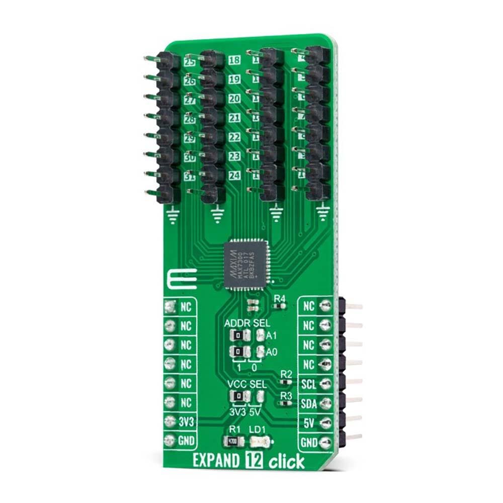
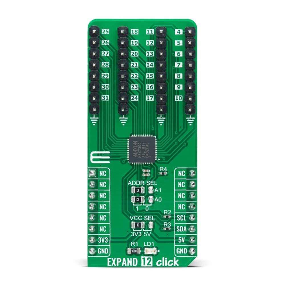
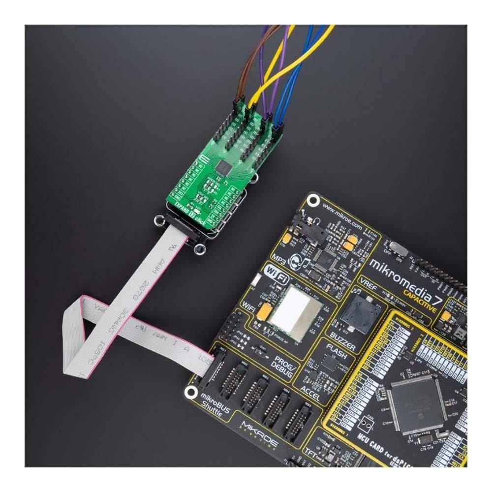
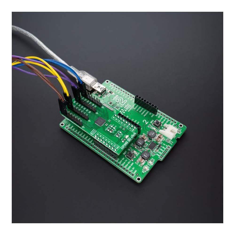
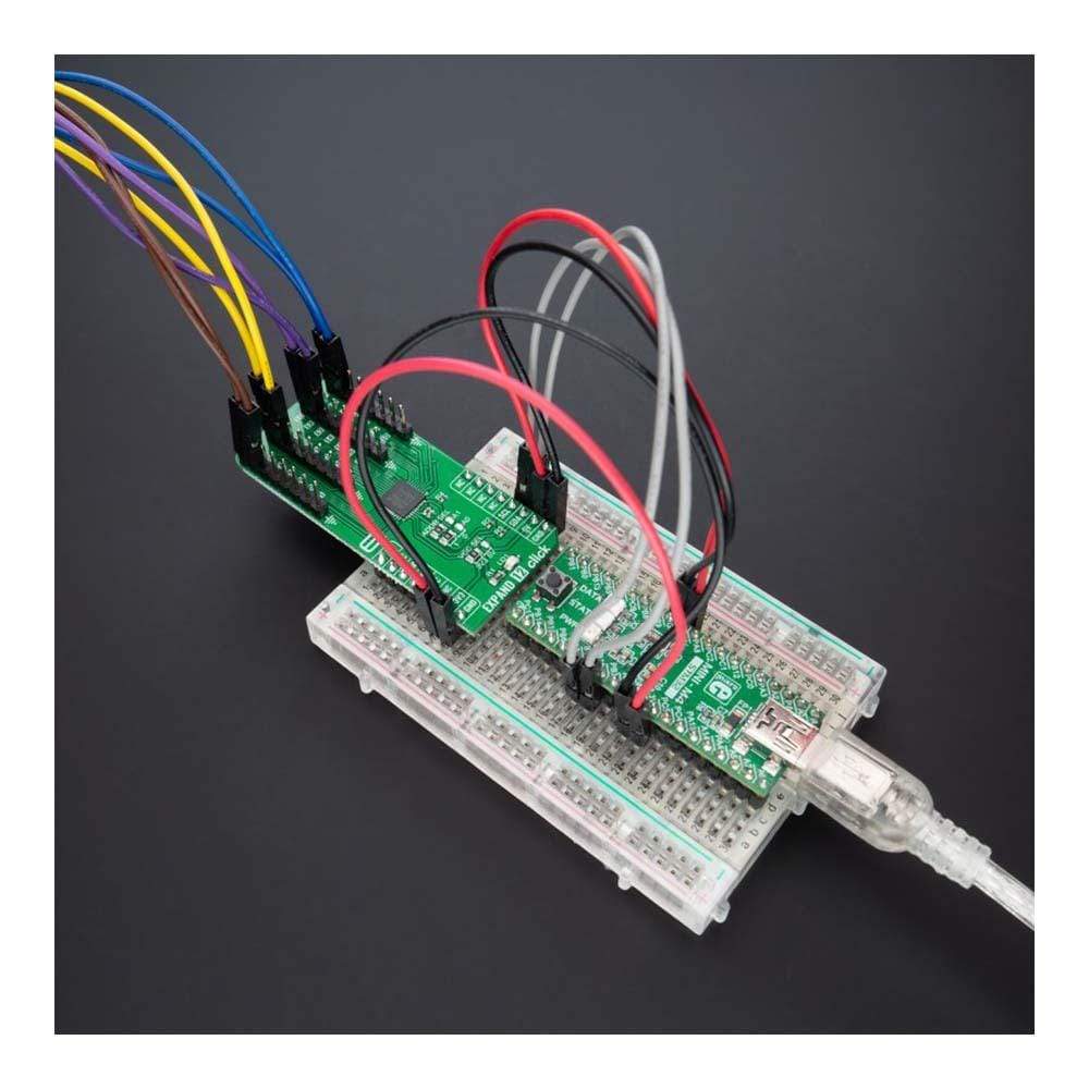
The Expand 12 Click Board™ is a compact add-on board that contains a multi-port I/O expander. This board features the MAX7300, a general-purpose I/O expander providing remote I/O expansion for most MCU’s families from Maxim Integrated, now part of Analog Devices. The MAX7300 comes in a 28-port configuration and allows easy addition of I/O through a standard I2C serial interface. Each port is user-configurable to either a logic input or logic output, capable of sinking 10mA and sourcing 4.5mA. In addition, seven ports feature configurable transition detection logic, which generates an interrupt upon change of port logic level.
The Expand 12 Click Board™ provides a simple solution when additional I/Os are needed while keeping interconnections to a minimum in system monitoring applications, industrial controllers, portable equipment, and many more.
Downloads
Der Expand 12 Click Board™ ist eine kompakte Zusatzkarte, die einen Multiport-E/A-Expander enthält. Diese Karte enthält den MAX7300, einen universellen E/A-Expander, der eine Remote-E/A-Erweiterung für die meisten MCU-Familien von Maxim Integrated, jetzt Teil von Analog Devices, bietet. Der MAX7300 ist in einer 28-Port-Konfiguration erhältlich und ermöglicht das einfache Hinzufügen von E/A über eine standardmäßige serielle I2C-Schnittstelle. Jeder Port ist vom Benutzer entweder als Logikeingang oder Logikausgang konfigurierbar und kann 10 mA aufnehmen und 4,5 mA liefern. Darüber hinaus verfügen sieben Ports über eine konfigurierbare Übergangserkennungslogik, die bei Änderung des Port-Logikpegels einen Interrupt generiert.
Das Expand 12 Click Board™ bietet eine einfache Lösung, wenn zusätzliche E/As benötigt werden und gleichzeitig die Verbindungen in Systemüberwachungsanwendungen, Industriesteuerungen, tragbaren Geräten und vielem mehr auf ein Minimum beschränkt bleiben.
| General Information | |
|---|---|
Part Number (SKU) |
MIKROE-4889
|
Manufacturer |
|
| Physical and Mechanical | |
Weight |
0.02 kg
|
| Other | |
EAN |
8606027384332
|
Frequently Asked Questions
Have a Question?
Be the first to ask a question about this.