


Mikroelektronika d.o.o.
Buck 16 Klickbrett
Buck 16 Klickbrett
SKU: MIKROE-4846
Verfügbarkeit für Abholungen konnte nicht geladen werden

Overview
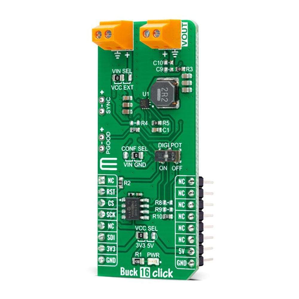
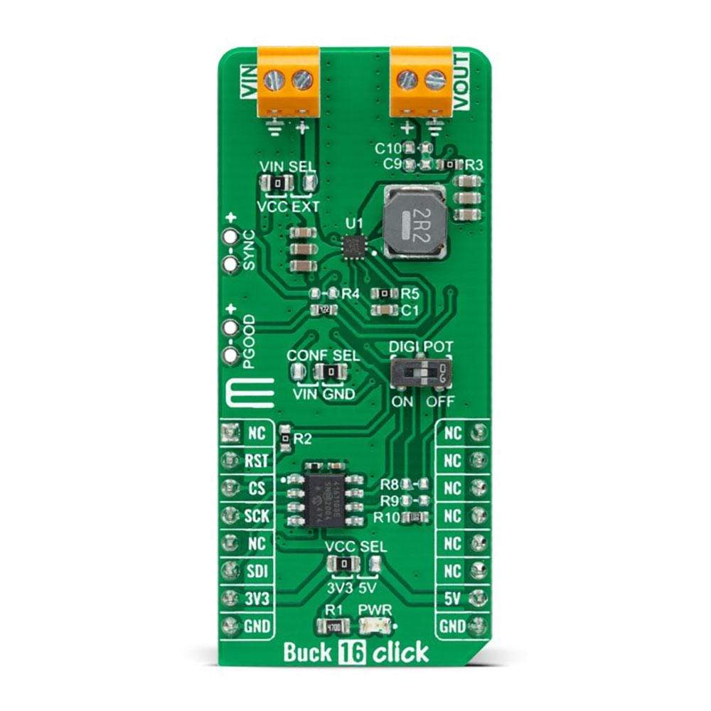
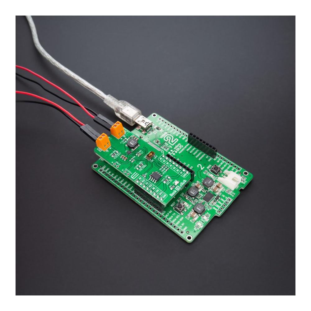
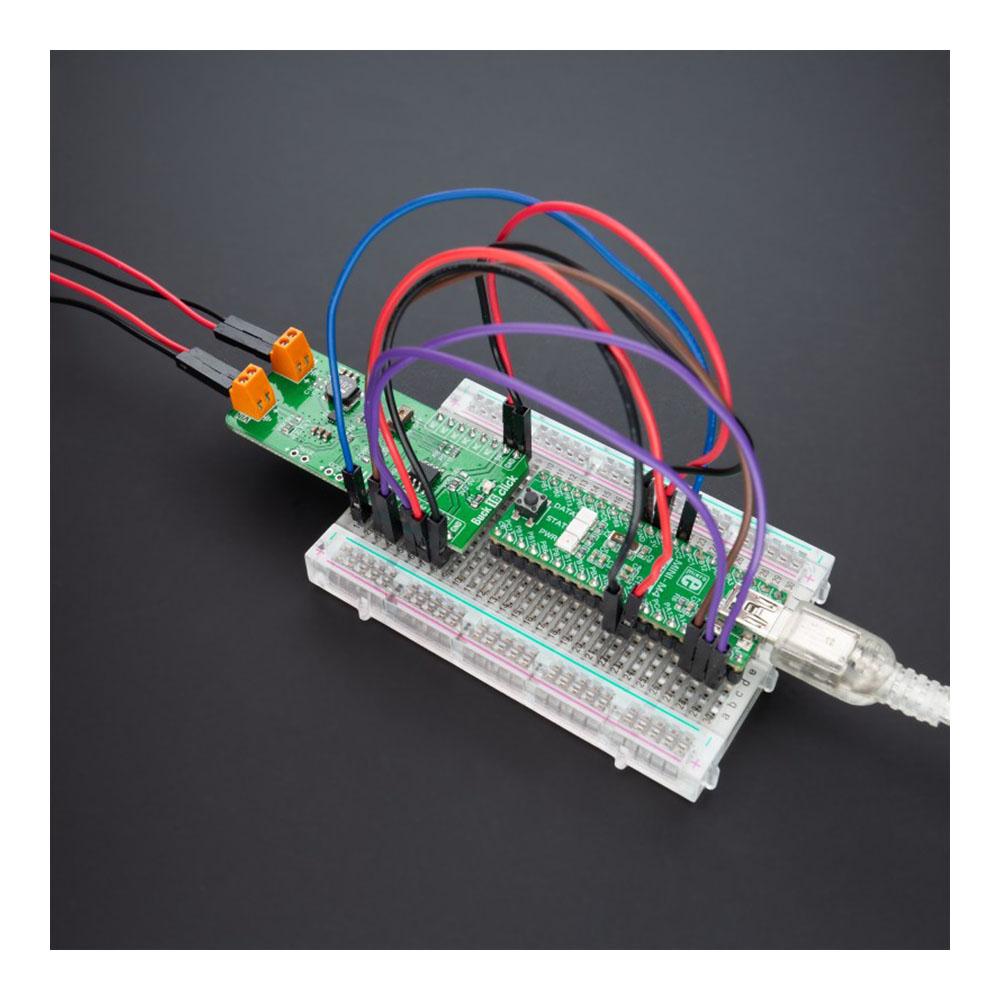
The Buck 16 Click Board™ is a compact add-on board that contains a DC-DC power converter that steps down the voltage from its input to its output. This board features the TPS62912, a high-efficiency, low noise, and low ripple current-mode synchronous buck converter from Texas Instruments. The TPS62912 has an output-voltage error of less than 1%, which helps ensure tight output-voltage accuracy, operates at a fixed switching frequency of 2.2MHz or 1MHz, and allows synchronization to an external clock.
The Buck 16 Click Board™ is suitable for noise-sensitive applications that generally use an LDO for post-regulation, such as high-speed ADCs, clock and jitter cleaner, serializer, de-serializer, and radar applications.
Downloads
Der Buck 16 Click Board™ ist eine kompakte Zusatzplatine, die einen DC-DC-Stromrichter enthält, der die Spannung von seinem Eingang zu seinem Ausgang heruntersetzt. Diese Platine verfügt über den TPS62912, einen hocheffizienten, rauscharmen und strombetriebenen synchronen Abwärtswandler von Texas Instruments mit geringer Welligkeit. Der TPS62912 hat einen Ausgangsspannungsfehler von weniger als 1 %, was eine hohe Ausgangsspannungsgenauigkeit gewährleistet, arbeitet mit einer festen Schaltfrequenz von 2,2 MHz oder 1 MHz und ermöglicht die Synchronisierung mit einer externen Uhr.
Das Buck 16 Click Board™ eignet sich für rauschempfindliche Anwendungen, die im Allgemeinen einen LDO zur Nachregelung verwenden, wie z. B. Hochgeschwindigkeits-ADCs, Takt- und Jitter-Cleaner, Serialisierer, Deserialisierer und Radaranwendungen.
| General Information | |
|---|---|
Part Number (SKU) |
MIKROE-4846
|
Manufacturer |
|
| Physical and Mechanical | |
Weight |
0.02 kg
|
| Other | |
EAN |
8606027383984
|
Frequently Asked Questions
Have a Question?
Be the first to ask a question about this.