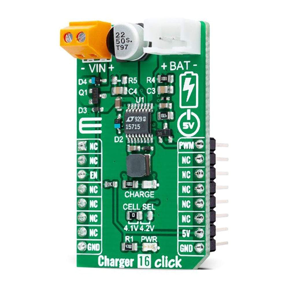
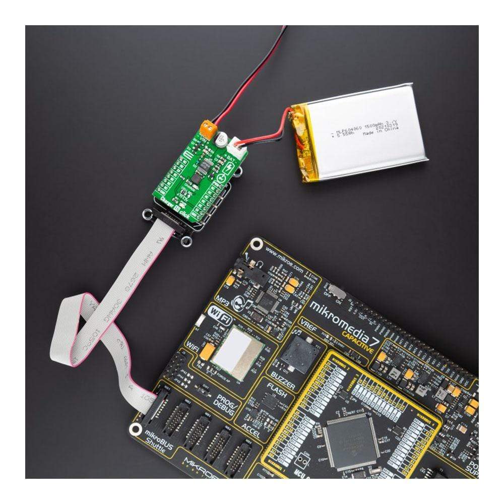
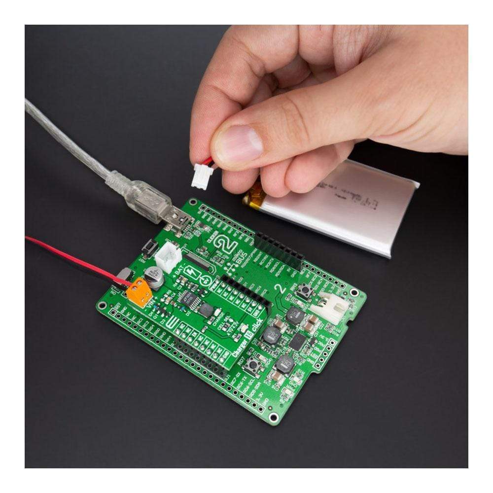
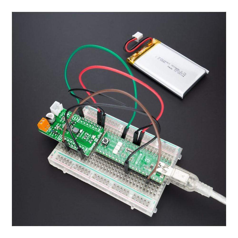
Ladegerät 16 Click-Platine
Overview
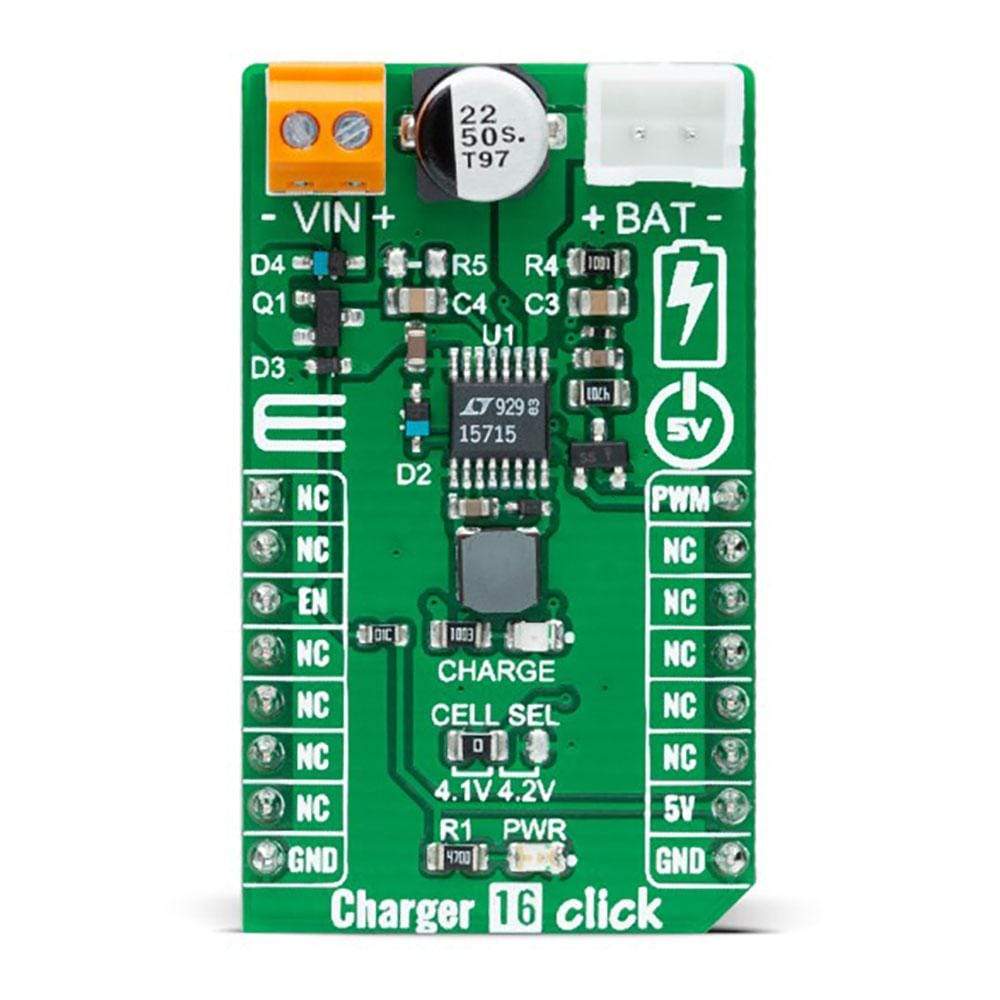
Der Ladegerät 16 Click Board™ ist eine kompakte Zusatzplatine, die ein Einzelzellen-Akkuladegerät darstellt. Diese Platine verfügt über den LT1571, ein Akkuladegerät mit konstantem Strom/konstanter Spannung mit voreingestellter Spannung und Abschlussflagge von Analog Devices. Dieses Click Board™ wird über eine externe Stromversorgung mit bis zu 20 V versorgt und verfügt über einen integrierten Strommesswiderstand, der eine einfache Programmierung des Ladestroms mit einer Genauigkeit von 5 % ermöglicht. Der interne Schalter kann 1,5 A Gleichstrom (2 A Spitzenstrom) liefern. Es verfügt außerdem über eine Anzeige für den nahezu vollen Ladezustand des Akkus, wenn der Ladestrom auf 20 % des programmierten Werts abfällt, und eine wählbare Konstantspannung für 4,1 V oder 4,2 V pro Zelle mit einer Genauigkeit von 0,6 %. Dieses Click Board™ eignet sich als Li-Ion-, NiMH- und NiCd-Akkuladegerät für tragbare Geräte und Zubehör, Elektrowerkzeuge und mehr.
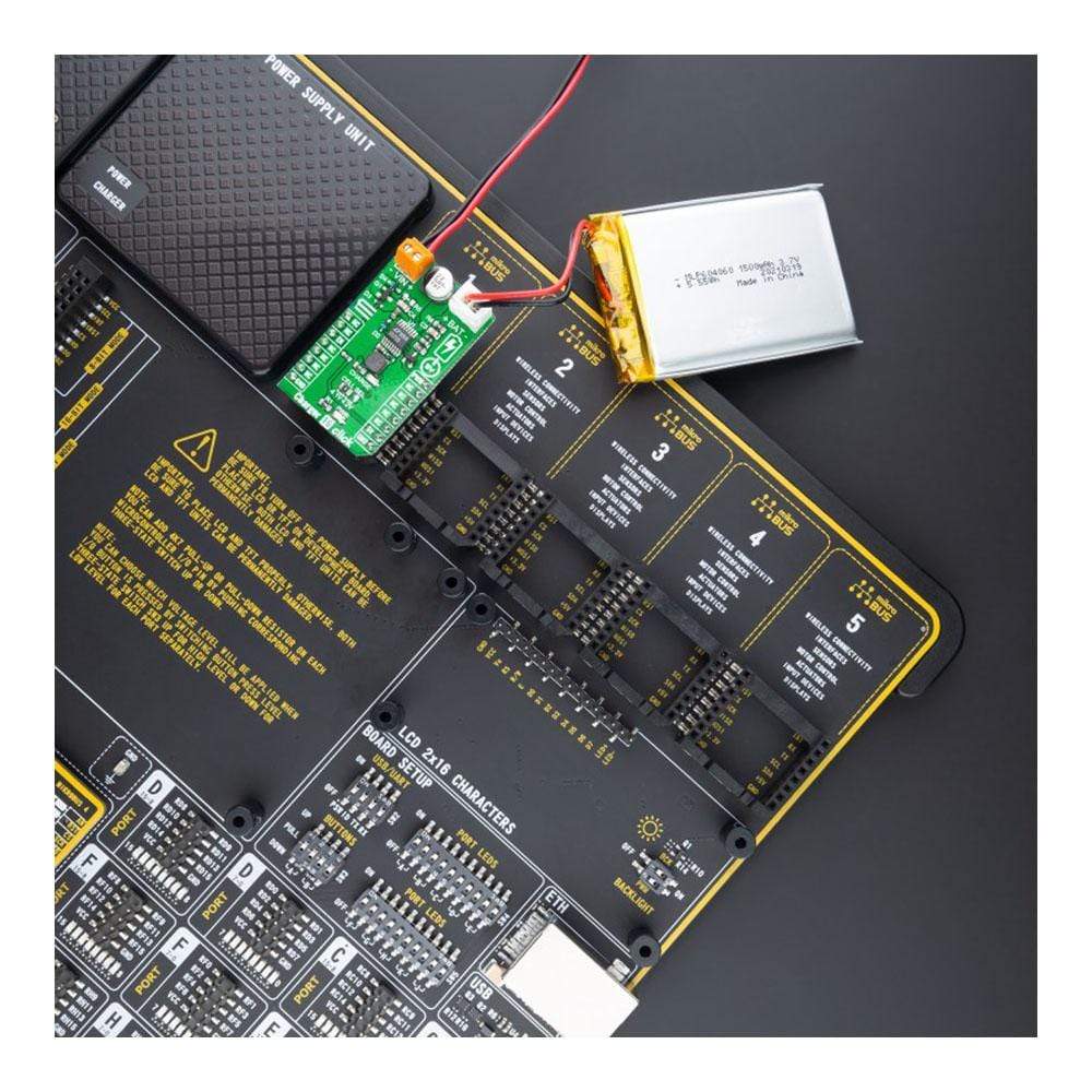
Das Charger 16 Click Board™ wird von einer mikroSDK-kompatiblen Bibliothek unterstützt, die Funktionen enthält, die die Softwareentwicklung vereinfachen. Dieses Click Board™ wird als vollständig getestetes Produkt geliefert und ist bereit für den Einsatz auf einem System, das mit der mikroBUS™-Buchse ausgestattet ist.
How Does The Charger 16 Click Board™ Work?
The Charger 16 Click Board™ as its foundation uses the LT1571, a current-mode PWM step-down (buck) charger from Analog Devices. This battery charger represents a simple, efficient solution to fast-charge rechargeable batteries, including lithium-ion (Li-Ion), nickel-metal-hydride (NiMH), and nickel-cadmium (NiCd) using constant-current and/or constant-voltage control. The internal switch is capable of delivering a 1.5A DC (2A peak current). A saturating switch operates at 500kHz, which provides high efficiency and a small charger size.
The Charger 16 Click Board™ communicates with MCU using two GPIO pins. The Enable pin, labeled as EN and routed to the CS pin of the mikroBUS™ socket, optimizes power consumption and is used for power ON/OFF purposes (driver operation permission). The onboard current sense resistor (R7) allows simple charge current programming to within 5% accuracy. Charge current can be programmed with the PWM from the mikroBUS™ socket by pulse width modulating current on a PROG pin with a switch Q2 to R7 at a frequency higher than a few kHz. Charge current will be proportional to the duty cycle of Q2 with full-current at 100% duty cycle.
This Click board™ also comes with an indication, red LED labeled as CHARGE, for battery near full-charge state, when the charge current drops to 20% of the programmed value, and selectable constant voltage for 4.1V or 4.2V per cell with 0.6% accuracy. Selection can be performed by onboard SMD jumper labeled as CELL SEL. Besides, the charge termination-flag threshold can be reduced from the default 20% level to as low as 7.5% of the programmed full charge current by positioning an onboard R5 resistor of appropriate value.
The Charger 16 Click Board™ supports an external power supply for the LT1571, which can be connected to the input terminal labeled as VIN and should be within the range of 8V to 20V. When the input voltage is removed, its supply voltage pin drops to 0.7V below the battery voltage forcing the charger into a low-battery drain (5mA typical) Sleep mode.
This Click board™ operates only with a 5V logic voltage level. The board must perform appropriate logic voltage level conversion before use with MCUs with different logic levels. However, the Click board™ comes equipped with a library containing functions and an example code that can be used, as a reference, for further development.
Specifications
Type | Battery charger |
Applications | Can be used as a Li-Ion, NiMH, NiCd battery charger for portable devices and accessories, power tools, and more |
On-board modules | LT1571 - constant-current/constant-voltage battery charger with preset voltage and termination flag from Analog Devices |
Key Features | Low power consumption, low shutdown current, fast charging of Li-Ion, NiMH and NiCd batteries, simple charge current programming, high efficency up to 1.5A charge current, battery voltage selection, battery charging indication, and more |
Interface | GPIO,PWM |
Compatibility | mikroBUS |
Click board size | M (42.9 x 25.4 mm) |
Input Voltage | 5V,External |
Pinout diagram
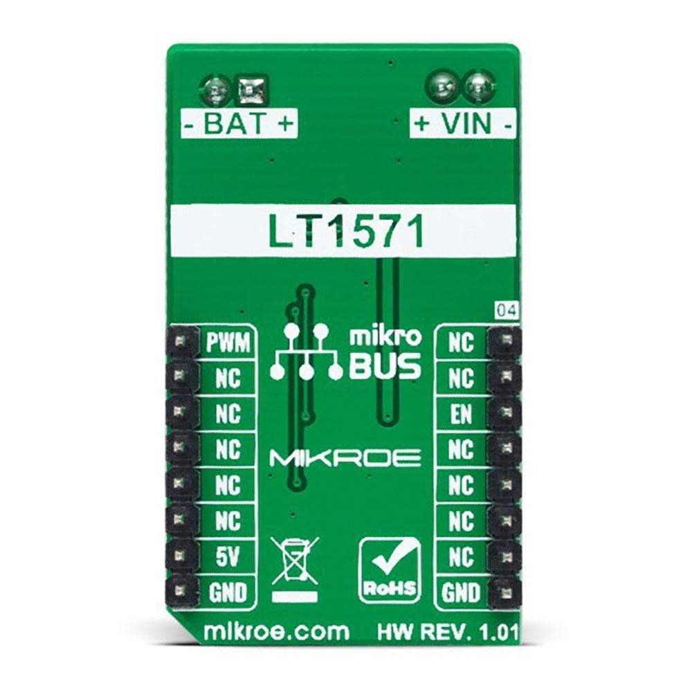
This table shows how the pinout on Charger 16 Click corresponds to the pinout on the mikroBUS™ socket (the latter shown in the two middle columns).
Notes | Pin | Pin | Notes | ||||
---|---|---|---|---|---|---|---|
NC | 1 | AN | PWM | 16 | PWM | PWM Signal | |
NC | 2 | RST | INT | 15 | NC | ||
Enable | EN | 3 | CS | RX | 14 | NC | |
NC | 4 | SCK | TX | 13 | NC | ||
NC | 5 | MISO | SCL | 12 | NC | ||
NC | 6 | MOSI | SDA | 11 | NC | ||
NC | 7 | 3.3V | 5V | 10 | 5V | Power Supply | |
Ground | GND | 8 | GND | GND | 9 | GND | Ground |
Onboard settings and indicators
Label | Name | Default | Description |
---|---|---|---|
LD1 | PWR | - | Power LED Indicator |
LD2 | CHARGE | - | Charging LED Indicator |
JP1 | CELL SEL | Left | Battery Voltage Selection 4.1V/4.2V: Left position 4.1V, Right position 4.2V |
R5 | R5 | Unpopulated | Charge Terminaltion-Flag Threshold Jumper |
Charger 16 Click electrical specifications
Description | Min | Typ | Max | Unit |
---|---|---|---|---|
Supply Voltage VCC | - | 5 | - | V |
External Supply Voltage VIN | 8 | - | 20 | V |
Output Current | - | - | 1.5 | A |
Battery Output Voltage | - | 4.1/4.2 | - | V |
Operating Temperature Range | -40 | +25 | +85 | °C |
We provide a library for the Charger 16 Click Board™ as well as a demo application (example), developed using MikroElektronika compilers. The demo can run on all the main MikroElektronika development boards.
The package can be downloaded/installed directly from NECTO Studio Package Manager(recommended way), downloaded from our LibStock™ or found on Mikroe Github account.
Library Description
This library contains API for the Charger 16 Click Board™ driver.
Key Functions
charger16_cfg_setup
- Config Object Initialization function.charger16_init
- Initialization function.charger16_default_cfg
- Click Default Configuration function.
Example Description
This library contains API for the Charger 16 Click Board™ driver. This demo application shows use of a Charger 16 Click Board™.
void application_task ( void ) { log_printf( &logger, "-----------------rn" ); log_printf( &logger, " Enable charging rn" ); charger16_enable_charging( &charger16 ); Delay_ms( 10000 ); log_printf( &logger, "------------------rn" ); log_printf( &logger, " Disable charging rn" ); charger16_disable_charging( &charger16 ); Delay_ms( 10000 ); }
The full application code, and ready to use projects can be installed directly from NECTO Studio Package Manager(recommended way), downloaded from our LibStock™ or found on Mikroe Github account.
Other Mikroe Libraries used in the example:
- MikroSDK.Board
- MikroSDK.Log
- Click.Charger16
Additional Notes and Information
Depending on the development board you are using, you may need a USB UART click, USB UART 2 click or RS232 click to connect to your PC, for development systems with no UART to USB interface available on the board. The terminal available in all MikroElektronika compilers, or any other terminal application of your choice, can be used to read the message.
mikroSDK
The Charger 16 Click Board™ is supported with mikroSDK - MikroElektronika Software Development Kit. To ensure proper operation of mikroSDK compliant Click board™ demo applications, mikroSDK should be downloaded from the LibStock and installed for the compiler you are using.
Frequently Asked Questions
Have a Question?
Be the first to ask a question about this.