


Mikroelektronika d.o.o.
ISO ADC 5 Click-Platine
ISO ADC 5 Click-Platine
SKU: MIKROE-4758
Verfügbarkeit für Abholungen konnte nicht geladen werden
Overview
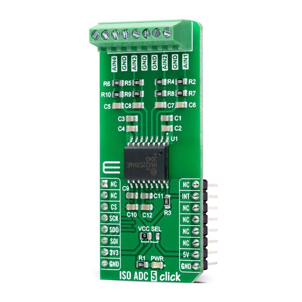
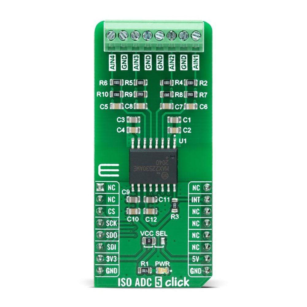
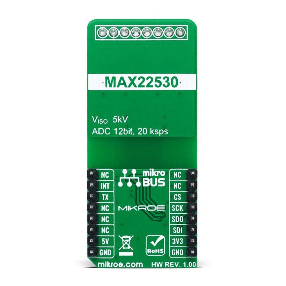
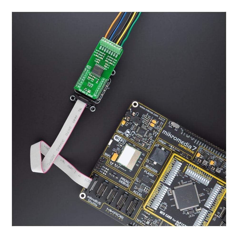
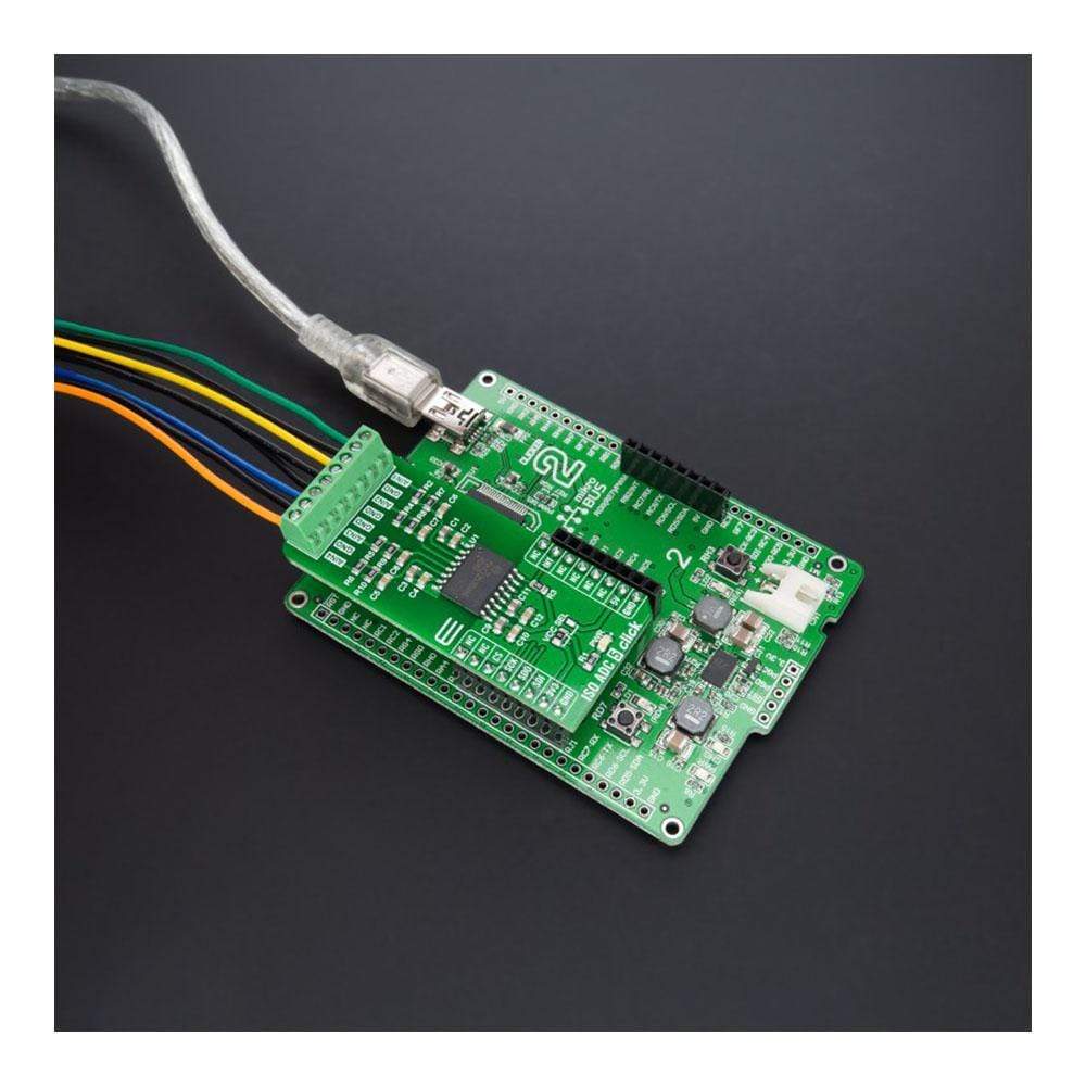
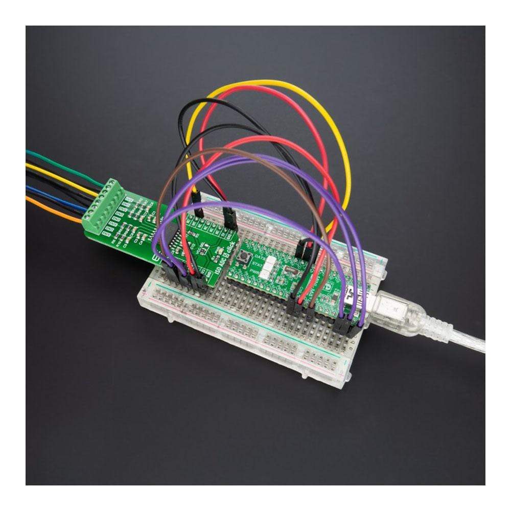
The ISO ADC 5 Click Board™ is a compact add-on board that contains quad-channel isolated ADC with field supply. This board features the MAX22530, galvanically isolated, 4-channel, multiplexed, 12-bit, analogue-to-digital converter (ADC), providing 5kVRMS isolation from Maxim Integrated. The ADC and all field-side circuits are powered by an integrated, isolated DC-DC converter that can verify field-side functionality even when there is no input signal or other field-side supply. The 12-bit ADC core has a sample rate of typically 20ksps per channel, where ADC data is available through the SPI interface. This Click Board™ is ideal for high-density, multi-range, group-isolated, binary-input modules and provides a complete solution to any system requiring monitoring inputs without a separate isolated power supply.
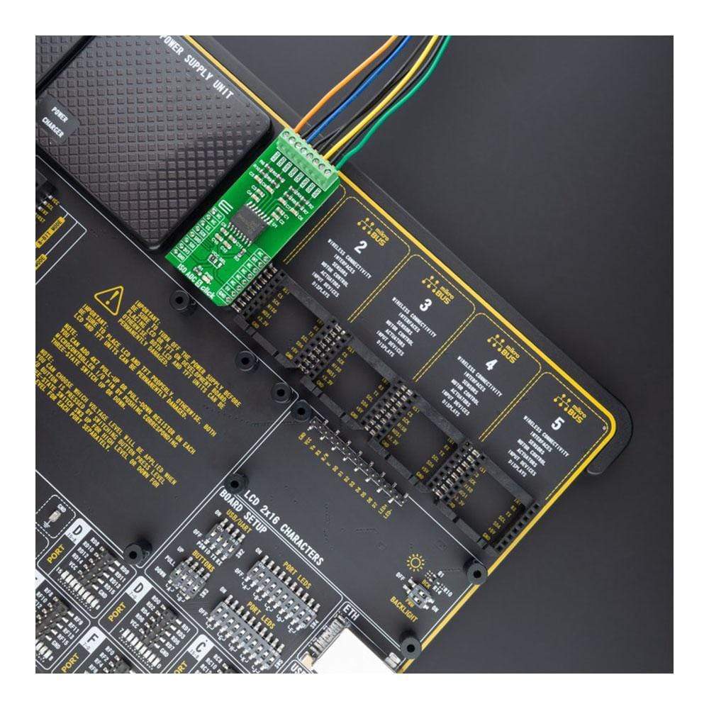
The ISO ADC 5 Click Board™ is supported by a mikroSDK compliant library, which includes functions that simplify software development. This Click Board™ comes as a fully tested product, ready to be used on a system equipped with the mikroBUS™ socket.
Downloads
Der ISO ADC 5 Click Board™ ist eine kompakte Zusatzplatine, die einen isolierten Vierkanal-ADC mit Feldversorgung enthält. Diese Platine verfügt über den galvanisch isolierten, 4-Kanal-, Multiplex-, 12-Bit-Analog-Digital-Wandler (ADC) MAX22530 mit 5 kVRMS-Isolierung von Maxim Integrated. Der ADC und alle feldseitigen Schaltkreise werden von einem integrierten, isolierten DC/DC-Wandler versorgt, der die feldseitige Funktionalität auch dann überprüfen kann, wenn kein Eingangssignal oder keine andere feldseitige Versorgung vorhanden ist. Der 12-Bit-ADC-Kern hat eine Abtastrate von typischerweise 20 kSps pro Kanal, wobei ADC-Daten über die SPI-Schnittstelle verfügbar sind. Dieses Click Board™ ist ideal für hochdichte, mehrbereichige, gruppenisolierte Binäreingangsmodule und bietet eine Komplettlösung für jedes System, das Überwachungseingänge ohne separate isolierte Stromversorgung erfordert.
Der ISO ADC 5 Click Board™ wird durch eine mikroSDK-kompatible Bibliothek unterstützt, die Funktionen enthält, die die Softwareentwicklung vereinfachen. Dieses Click Board™ wird als vollständig getestetes Produkt geliefert und ist bereit für den Einsatz auf einem System, das mit der mikroBUS™-Buchse ausgestattet ist.
| General Information | |
|---|---|
Part Number (SKU) |
MIKROE-4758
|
Manufacturer |
|
| Physical and Mechanical | |
Weight |
0.02 kg
|
| Other | |
EAN |
8606027383465
|
Frequently Asked Questions
Have a Question?
Be the first to ask a question about this.