MUX 4 Click-Platine
MUX 4 Click-Platine
Overview
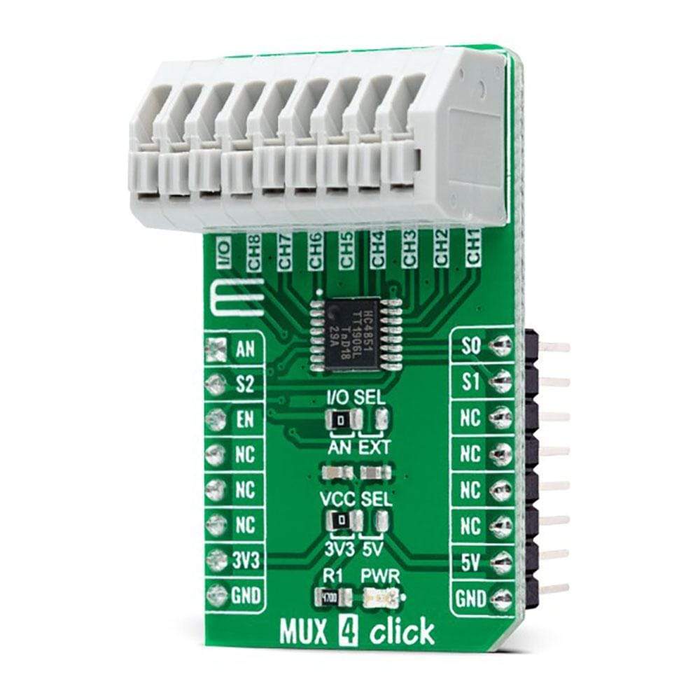
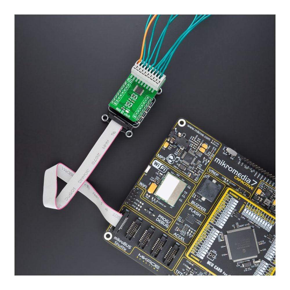
Der MUX 4 Click Board™ ist eine kompakte Zusatzplatine, die einen präzisen analogen Multiplexing-IC enthält. Diese Platine verfügt über den 74HC4851, einen 8-Kanal-Analog-Multiplexer/Demultiplexer mit Injektionsstromeffektsteuerung von Nexperia USA Inc. Dieses Click Board™ verfügt über drei digitale Auswahleingänge, einen Active-LOW-Freigabeeingang, acht unabhängige Ein-/Ausgänge und einen gemeinsamen Eingang/Ausgang. Es verfügt außerdem über eine Injektionsstromeffektsteuerung, die sich hervorragend für Automobilanwendungen eignet, bei denen Spannungen über der Versorgungsspannung üblich sind. Dieses Click Board™ eignet sich für eine Vielzahl von analogen oder digitalen Mux/Demux-Anwendungen, von Industrie- und Instrumentierungs- bis hin zu Verbraucher-, Kommunikations- und Automobilsystemen.
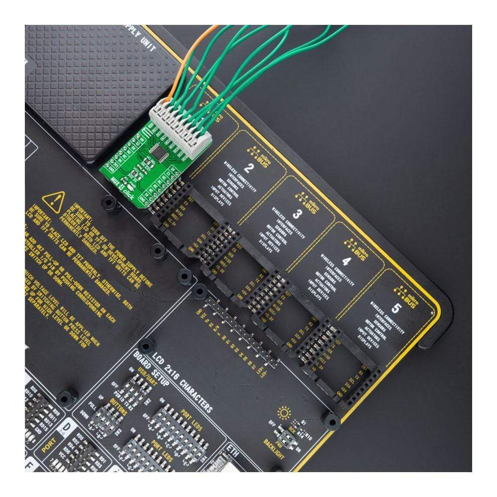
Der MUX 4 Click Board™ wird durch eine mikroSDK-kompatible Bibliothek unterstützt, die Funktionen enthält, die die Softwareentwicklung vereinfachen. Dieses Click Board™ wird als vollständig getestetes Produkt geliefert und ist bereit für den Einsatz auf einem System, das mit der mikroBUS™-Buchse ausgestattet ist.
How Does The MUX 4 Click Board™ Work?
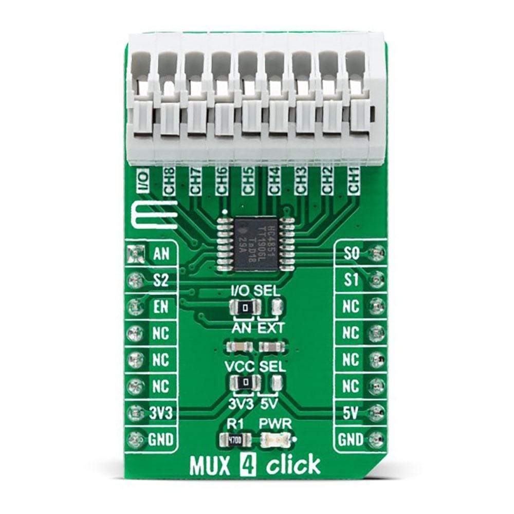
The MUX 4 Click Board™ as its foundation uses the 74HC4851, a precise 8-channel analog multiplexer/demultiplexer from Nexperia USA Inc. The 74HC4851 comes with eight independent input/output channels labeled from CH1 to CH8 that accept analog and digital signals of any voltage up to 5V. Compared to its predecessors, the 74HC4851 is better to use for the simple reason that it has a higher tolerance to a disturbance on channels that are not connected. Thanks to its characteristic of being both a multiplexer and a demultiplexer, the signals can travel in both directions.
The injection-current effect control, which is integrated inside the 74HC4851, allows signals at disabled analog input channels to exceed the supply voltage without affecting the signal of the enabled analog channel. This feature eliminates the need for external diode/resistor networks typically used to keep the analog channel signals within the supply-voltage range.
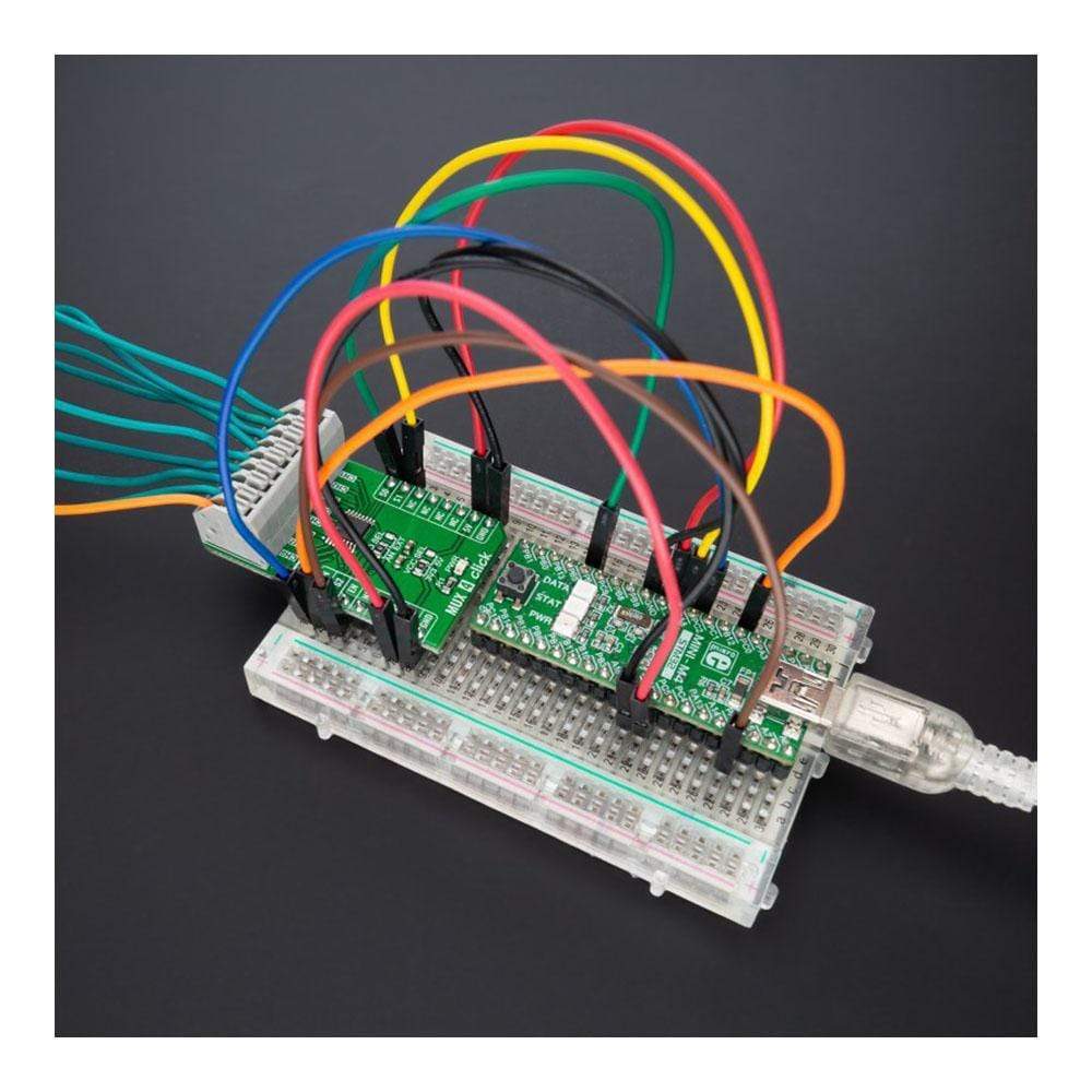
MUX 4 Click communicates with MCU using several GPIO pins. With EN pin, routed to the CS pin on the mikroBUS™ socket, is set to its low logic state, one of the eight switches is selected by three pins labeled as S0, S1, and S2 routed to the RST, PWM, and INT pins on the mikroBUS™ socket. With EN pin is set to its high logic state, all switches are in the high-impedance OFF-state, independent of S0 to S2 pins.
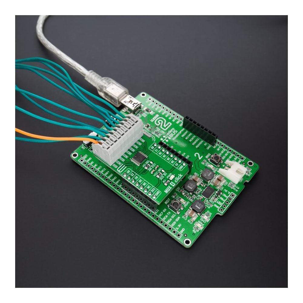
In addition to its eight independent input/output pins, the 74HC4851 also has a common input/output pin where it is possible to select the signal input to a given pin, more precisely, whether the signal will be brought externally from the terminal labeled as I/O or from mikroBUS™ socket AN pin. Selection can be performed by onboard SMD jumper labeled as I/O SEL to an appropriate position marked as AN and EXT. The MUX 4 Click comes equipped with one nine-position spring terminal for all input/output signals, making all wire connections reliable and straightforward.
The MUX 4 Click Board™ can operate with both 3.3V and 5V logic voltage levels selected via the VCC SEL jumper. This way, it allows both 3.3V and 5V capable MCUs to use the communication lines properly. However, the Click board™ comes equipped with a library containing easy-to-use functions and an example code that can be used, as a reference, for further development.
Specifications
Type | DAC |
Applications | Can be used for a wide range of analog or digital mux/demux applications, from industrial and instrumentation, consumer, communications, and automotive systems |
On-board modules | 74HC4851 - precise 8-channel analog multiplexer/demultiplexer from Nexperia USA Inc |
Key Features | Low power consumption, injection-current effect control, high speed, pin-controllable, eight channels, common I/O channel signal selection, and more |
Interface | Analog,GPIO |
Compatibility | mikroBUS |
Click board size | M (42.9 x 25.4 mm) |
Input Voltage | 3.3V or 5V |
Pinout diagram
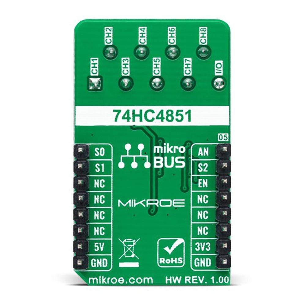
This table shows how the pinout on MUX 4 Click corresponds to the pinout on the mikroBUS™ socket (the latter shown in the two middle columns).
Notes | Pin | Pin | Notes | ||||
---|---|---|---|---|---|---|---|
Analog Signal | AN | 1 | AN | PWM | 16 | S0 | Channel Selection |
Channel Selection | S2 | 2 | RST | INT | 15 | S1 | Channel Selection |
Enable | EN | 3 | CS | RX | 14 | NC | |
NC | 4 | SCK | TX | 13 | NC | ||
NC | 5 | MISO | SCL | 12 | NC | ||
NC | 6 | MOSI | SDA | 11 | NC | ||
Power Supply | 3.3V | 7 | 3.3V | 5V | 10 | 5V | Power Supply |
Ground | GND | 8 | GND | GND | 9 | GND | Ground |
Onboard settings and indicators
Label | Name | Default | Description |
---|---|---|---|
LD1 | PWR | - | Power LED Indicator |
JP1 | VCC SEL | Left | Logic Level Voltage Selection 3V3/5V: Left position 3V3, Right position 5V |
JP2 | I/0 SEL | Left | Common I/O Channel Signal Selection AN/EXT: Left position AN, Right position EXT |
MUX 4 Click Electrical Specifications
Description | Min | Typ | Max | Unit |
---|---|---|---|---|
Supply Voltage VCC | 3.3 | - | 5 | V |
Input Voltage Range | 0 | - | VCC | V |
ON Resistance (Peak) | - | - | 200 | Ω |
Operating Temperature Range | -40 | +25 | +85 | °C |
Software Support
We provide a library for the MUX 4 Click Board™ as well as a demo application (example), developed using MikroElektronika compilers. The demo can run on all the main MikroElektronika development boards.
Package can be downloaded/installed directly from NECTO Studio Package Manager(recommended way), downloaded from our LibStock™ or found on Mikroe Github account.
Library Description
This library contains API for MUX 4 Click driver.
Key Functions
mux4_cfg_setup
- Config Object Initialization function.mux4_init
- Initialization function.
Example Description
This example demonstrates the use of MUX 4 click board.
The demo application is composed of two sections :
void application_task ( void ) { float mux4_an_voltage = 0; for ( uint8_t cnt = MUX4_SELECT_INPUT_1; cnt <= MUX4_SELECT_INPUT_8; cnt++ ) { mux4_select_input( &mux4, cnt ); Delay_ms( 10 ); if ( ADC_ERROR != mux4_read_an_pin_voltage ( &mux4, &mux4_an_voltage ) ) { log_printf( &logger, " CH%u Voltage : %.3f Vrn", ( uint16_t ) cnt, mux4_an_voltage ); } } log_printf( &logger, " ----------------------------rn" ); Delay_ms( 1000 ); }
The full application code, and ready to use projects can be installed directly from NECTO Studio Package Manager(recommended way), downloaded from our LibStock™ or found on Mikroe github account.
Other Mikroe Libraries used in the example:
- MikroSDK.Board
- MikroSDK.Log
- Click.MUX4
Additional Notes and Information
Depending on the development board you are using, you may need USB UART click, USB UART 2 click or RS232 click to connect to your PC, for development systems with no UART to USB interface available on the board. The terminal available in all MikroElektronika compilers, or any other terminal application of your choice, can be used to read the message.
mikroSDK
This Click board™ is supported with mikroSDK - MikroElektronika Software Development Kit. To ensure proper operation of mikroSDK compliant Click board™ demo applications, mikroSDK should be downloaded from the LibStock and installed for the compiler you are using.
Frequently Asked Questions
Have a Question?
Be the first to ask a question about this.