


Mikroelektronika d.o.o.
I2C-auf-CAN-Click-Platine
I2C-auf-CAN-Click-Platine
SKU: MIKROE-4644
Verfügbarkeit für Abholungen konnte nicht geladen werden


Overview
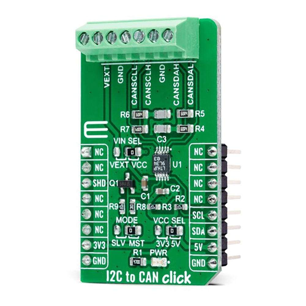
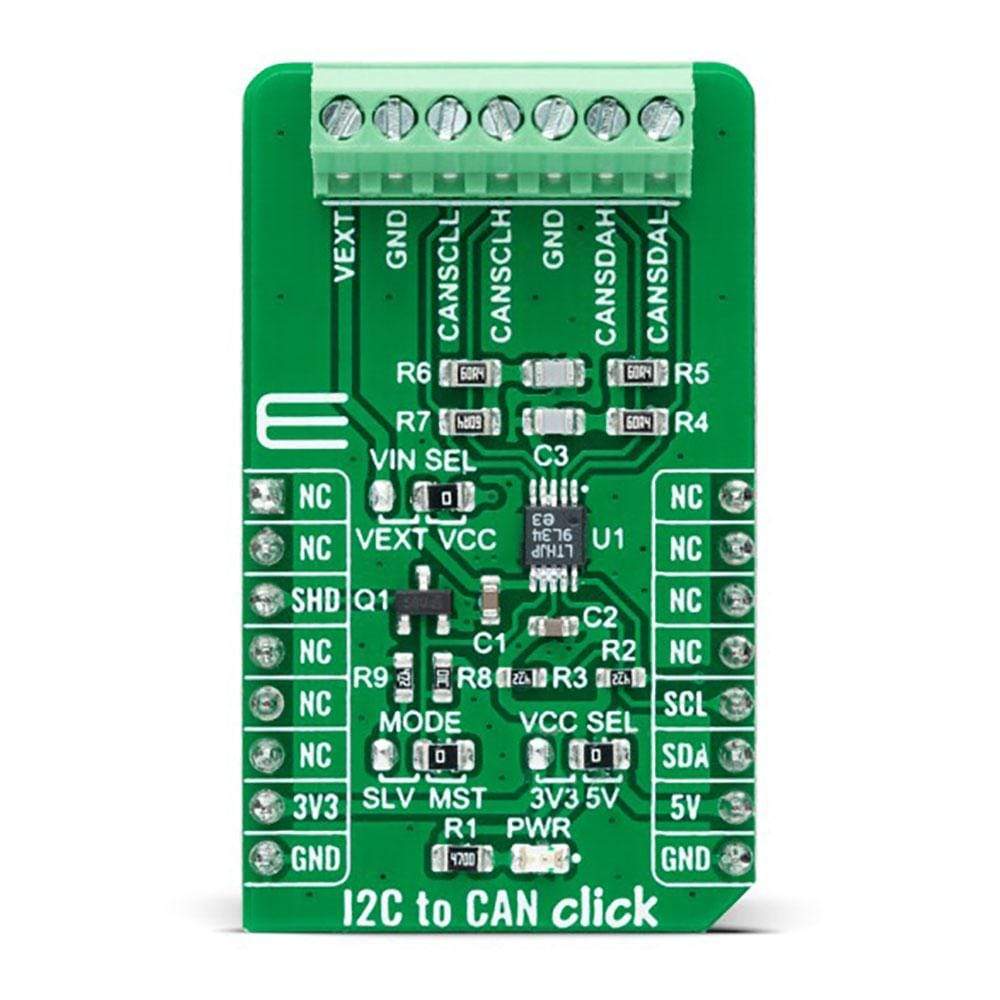
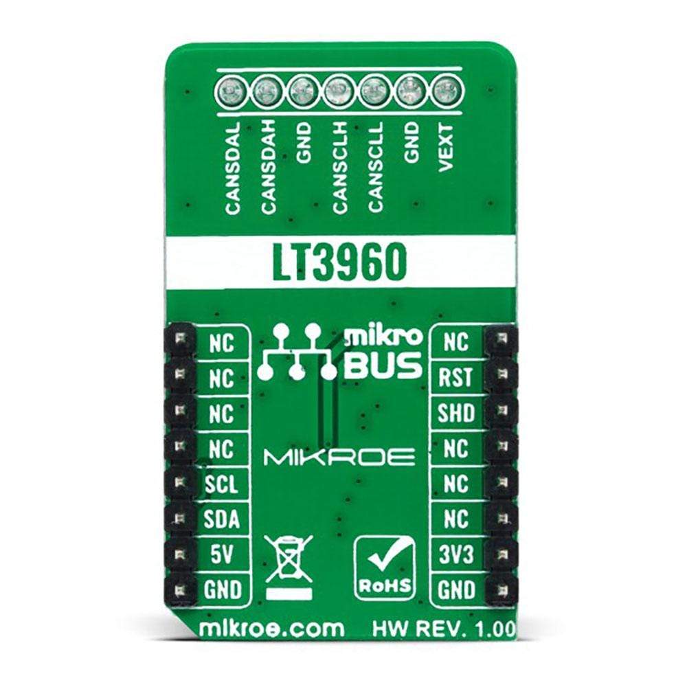
The I2C to CAN Click Board™ is a compact add-on board that contains I2C to CAN-physical transceiver, which extends a single-master I2C bus through harsh or noisy environments. This board features the LT3960, a robust high-speed transceiver that extends a single-master I2C bus up to 400kbps using the CAN-physical layer from Analog Devices. One LT3960 from SCL and SDA I2C lines creates equivalent differential buses (CAN) on two twisted pairs, while the second LT3960 recreates the I2C bus locally for any slave I2C devices on the other end of the twisted pairs. A built-in 3.3V LDO powers the I2C and CAN lines from a single input supply from 4V to 60V.
The I2C to CAN Click Board™ is suitable for industrial and automotive networking, remote sensor applications, and more.
Downloads
Das I2C to CAN Click Board™ ist eine kompakte Zusatzplatine, die einen I2C to CAN-physischen Transceiver enthält, der einen Single-Master-I2C-Bus durch raue oder laute Umgebungen erweitert. Diese Platine verfügt über den LT3960, einen robusten Hochgeschwindigkeits-Transceiver, der einen Single-Master-I2C-Bus mithilfe der CAN-physischen Schicht von Analog Devices auf bis zu 400 kbit/s erweitert. Ein LT3960 aus SCL- und SDA-I2C-Leitungen erstellt äquivalente Differenzbusse (CAN) auf zwei verdrillten Paaren, während der zweite LT3960 den I2C-Bus lokal für alle Slave-I2C-Geräte am anderen Ende der verdrillten Paare neu erstellt. Ein integrierter 3,3-V-LDO versorgt die I2C- und CAN-Leitungen über eine einzelne Eingangsversorgung von 4 V bis 60 V.
Das I2C-zu-CAN-Click-Board™ eignet sich für Industrie- und Automobilnetzwerke, Remote-Sensoranwendungen und mehr.
| General Information | |
|---|---|
Part Number (SKU) |
MIKROE-4644
|
Manufacturer |
|
| Physical and Mechanical | |
Weight |
0.02 kg
|
| Other | |
EAN |
8606027382864
|
Frequently Asked Questions
Have a Question?
Be the first to ask a question about this.