LR 4 Click-Platine
LR 4 Click-Platine
Overview
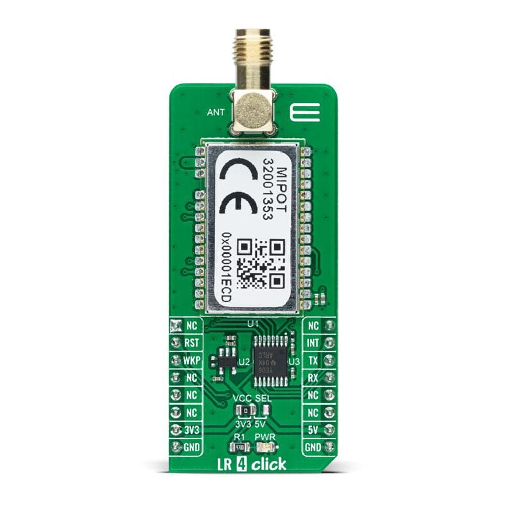
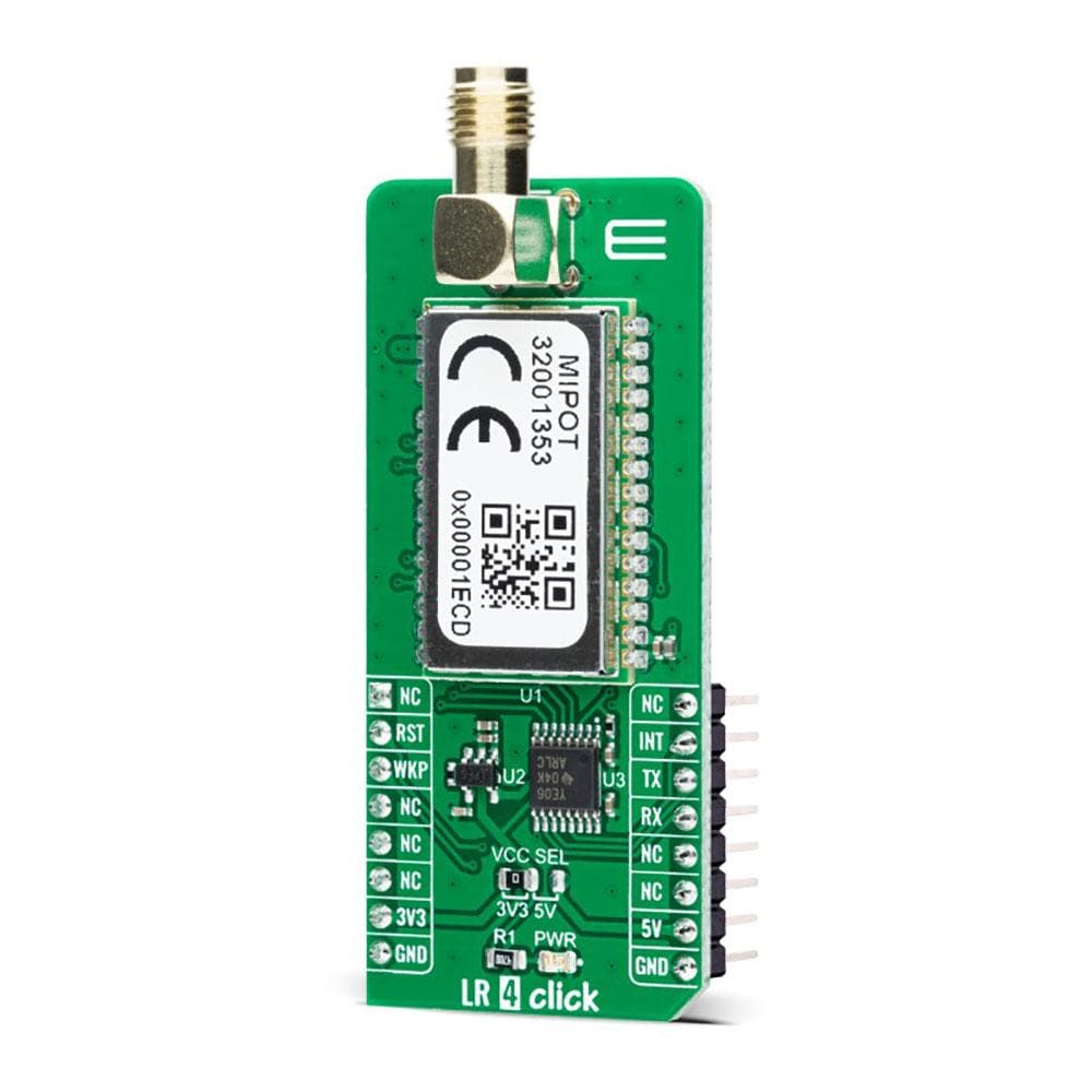
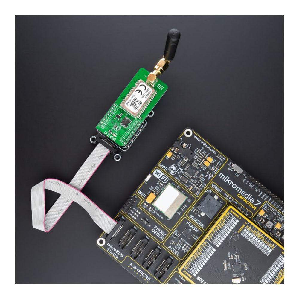
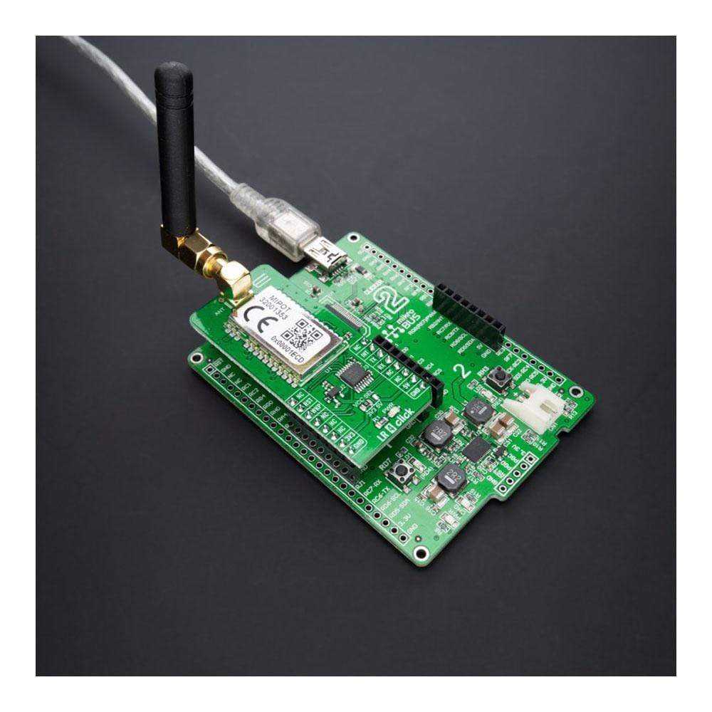
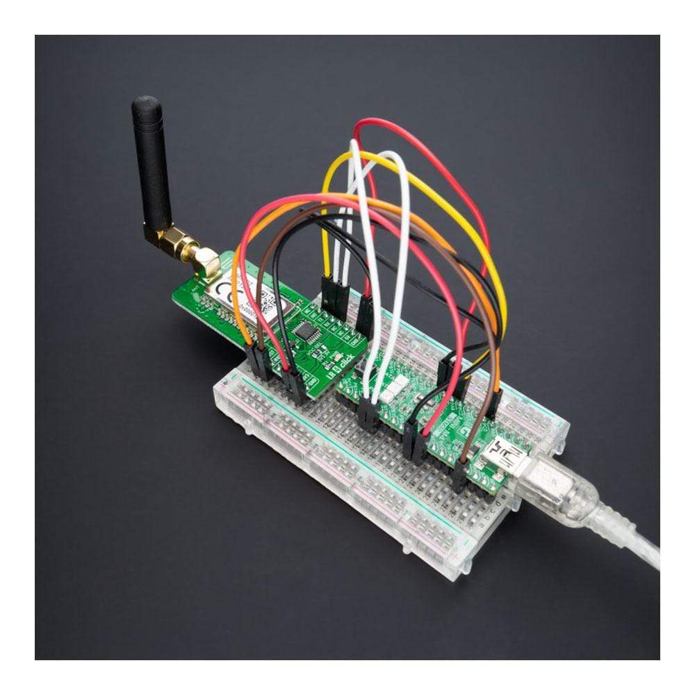
Das LR 4 Click Board™ ist eine kompakte Zusatzplatine, die einen Transceiver mit großer Reichweite enthält. Diese Platine verfügt über den 32001353, einen auf HF-Technologie basierenden SRD-Transceiver, der mit einer Frequenz von 868 MHz von Mipot betrieben wird. Dank der Spread-Spectrum-Modulationsfunktion sowie des geringen Stromverbrauchs ist eine störungsunempfindliche Kommunikation mit großer Reichweite möglich. Es verfügt über einen vollständigen Stapel mit großer Reichweite auf der Platine; es implementiert physische, Netzwerk- und MAC-Schichten und ermöglicht so eine einfache Bedienung über die UART-Schnittstelle. Der Transceiver ist außerdem RED 2014/53/EU-zertifiziert und ermöglicht so eine einfache Integration in die endgültige Anwendung. Dieses Click Board™ bietet eine einfache und zuverlässige Lösung für die Entwicklung hochintegrierter IoT-Netzwerke mit großer Reichweite, Sicherheitssysteme, Alarmnetzwerke und ähnliche Anwendungen, die einfache und zuverlässige Netzwerklösungen erfordern.
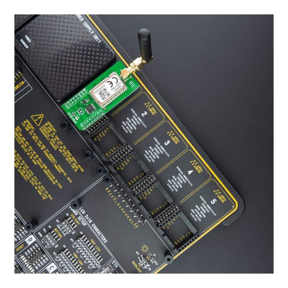
Das LR 4 Click Board™ wird durch eine mikroSDK-kompatible Bibliothek unterstützt, die Funktionen enthält, die die Softwareentwicklung vereinfachen. Dieses Click Board™ wird als vollständig getestetes Produkt geliefert und ist bereit für den Einsatz auf einem System, das mit der mikroBUS™-Buchse ausgestattet ist.
How Does The LR 4 Click Board™Work?
The LR 4 Click Board™ as its foundation uses the 32001353, a low-power long-range RF technology-based transceiver module from Mipot. It offers a long-range spread spectrum communication with high interference immunity. The network is implemented as a star topology, where endpoints work in duty cycle mode, significantly reducing the overall power consumption. The LR 4 Click Board™ features an embedded LoRaWAN Class A and Class C compliant stack offering an easy and reliable solution for developing low-power, highly integrated IoT networks, security systems, alarm networks, and similar applications that require simple and reliable networking solutions.
To join a LoRaWAN network, the 32001353 requires a LoRaWAN concentrator/gateway. The endpoint device has to use a unique endpoint address, an application session key, and a network session key. The first method is called over-the-air activation (OTAA), where these keys are issued after a specific join procedure. The second method is to assign these keys manually, using UART commands. This method is called activation by personalization (ABP) and can be prone to some security issues. In any case, before an end-device can communicate on the LoRaWAN network, it must be activated.
The LR 4 Click Board™ communicates with MCU using the UART interface with commonly used UART RX and TX pins at data rates up to 115200bps for the data transfer. In addition to these features, the 32001353 also uses several GPIO pins connected to the mikroBUS™ socket. The WK pin routed on the CS pin of the mikroBUS™ represents the Wake-up function used for waking up the device, while the RST pin on the mikroBUS™ socket can perform Hardware Reset function by putting this pin in a logic low state. This Click board™ also has an indicator routed on the INT pin of the mikroBUS ™ socket, which will provide the user with feedback after a successfully received package and verified checksum.
The LR 4 Click Board™ features the SMA antenna connector with an impedance of 50Ω, so it can be equipped with the appropriate 868MHz compliant antenna that MikroE has in its offer.
The LR 4 Click Board™can operate with both 3.3V and 5V logic voltage levels selected via the VCC SEL jumper. A proper logic voltage level conversion is performed by the TXB0106 voltage level shifter, while the LDO ensures that recommended values power the module. This allows for both 3.3V and 5V capable MCUs to use the UART communication lines properly. However, the Click board™ comes equipped with a library containing easy-to-use functions and an example code that can be used, as a reference, for further development.
SPECIFICATIONS
Type | LoRa |
Applications | The LR 4 Click Board™ can be used for developing highly integrated long-range IoT networks, security systems, alarm networks, and similar applications that require simple and reliable networking solutions. |
On-board modules | 32001353 - low-power long-range RF technology-based transceiver module from Mipot |
Radio Region | Europe |
Key Features | Low power consumption, RF technology based wireless networking, LoraWAN protocol, easy to use UART interface, and more. |
Interface | UART |
Compatibility | mikroBUS |
Click board size | L (57.15 x 25.4 mm) |
Input Voltage | 3.3V or 5V |
PINOUT DIAGRAM
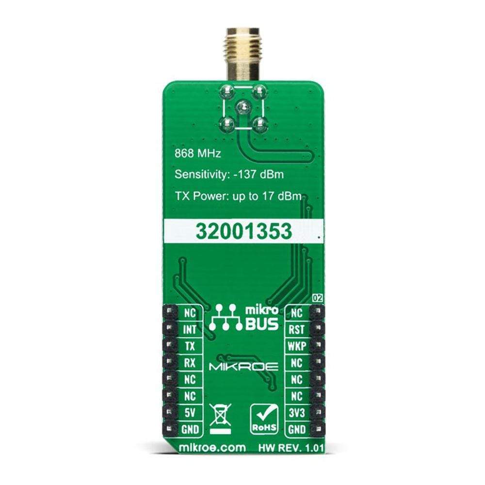
This table shows how the pinout of the LR 4 Click Board™ corresponds to the pinout on the mikroBUS™ socket (the latter shown in the two middle columns).
Notes | Pin | Pin | Notes | ||||
---|---|---|---|---|---|---|---|
NC | 1 | AN | PWM | 16 | NC | ||
Reset | RST | 2 | RST | INT | 15 | INT | Data TX Indication |
Wake-Up | WKP | 3 | CS | RX | 14 | TX | UART TX |
NC | 4 | SCK | TX | 13 | RX | UART RX | |
NC | 5 | MISO | SCL | 12 | NC | ||
NC | 6 | MOSI | SDA | 11 | NC | ||
Power Supply | 3.3V | 7 | 3.3V | 5V | 10 | 5V | Power Supply |
Ground | GND | 8 | GND | GND | 9 | GND | Ground |
ONBOARD SETTINGS AND INDICATORS
Label | Name | Default | Description |
---|---|---|---|
LD1 | PWR | - | Power LED Indicator |
JP1 | VCC SEL | Left | Logic Level Voltage Selection 3V3/5V: Left position 3V3, Right position 5V |
LR 4 CLICK ELECTRICAL SPECIFICATIONS
Description | Min | Typ | Max | Unit |
---|---|---|---|---|
Supply Voltage | 3.3 | - | 5 | V |
Operating Frequency Range | 863 | 868 | 870 | MHz |
Operating Temperature Range | -40 | +25 | +85 | °C |
Software Support
We provide a library for the LR 4 Click Board™ as well as a demo application (example), developed using MikroElektronika compilers. The demo can run on all the main MikroElektronika development boards.
The package can be downloaded/installed directly form compilers IDE(recommended way), or downloaded from our LibStock, or found on mikroE Github account.
Library Description
This library contains API for LR 4 Click driver.
Key Functions
void lr4_cfg_setup ( lr4_cfg_t *cfg );
- Config Object Initialization function.LR4_RETVAL lr4_init ( lr4_t *ctx, lr4_cfg_t *cfg );
- Initialization function.
Example Description
This example reads and processes data from the LR 4 Click Board™.
The demo application is composed of two sections :
void application_task ( void ) { log_printf( &logger, "Get Activation Status!rn" ); uint8_t status = lr4_get_status( &lr4, LR4_GET_ACTIVATION_MODE ); log_printf( &logger, "Status: " ); switch ( status ) { case LR4_STATUS_NOT_ACTIVATED : { log_printf( &logger, "Not activated.rn" ); break; } case LR4_STATUS_JOINING : { log_printf( &logger, "Joining...rn" ); break; } case LR4_STATUS_JOINED : { log_printf( &logger, "Joined.rn" ); break; } case LR4_STATUS_MAC_ERROR : { log_printf( &logger, "MAC ERROR.rn" ); break; } default : { break; } } log_printf( &logger, "------------------------rn" ); Delay_ms( 1000 ); log_printf( &logger, "Get Session Status!rn" ); status = lr4_get_status( &lr4, LR4_GET_SESSION_STATUS_MODE ); log_printf( &logger, "Status: " ); switch ( status ) { case LR4_STATUS_IDLE : { log_printf( &logger, "Idle.rn" ); break; } case LR4_STATUS_BUSY : { log_printf( &logger, "Busy (LR session running).rn" ); break; } case LR4_STATUS_DEV_NOT_ACTIVATED : { log_printf( &logger, "Device not activated.rn" ); break; } case LR4_STATUS_DELAYED : { log_printf( &logger, "Delayed (LR session paused due to Duty-cycle).rn" ); break; } default : { break; } } log_printf( &logger, "------------------------rn" ); Delay_ms( 1000 ); }
The full application code, and ready to use projects can be installed directly form compilers IDE(recommended) or found on LibStock page or mikroE GitHub account.
Other mikroE Libraries used in the example:
- MikroSDK.Board
- MikroSDK.Log
- Click.LR4
Additional Notes and Information
Depending on the development board you are using, you may need a USB UART click, USB UART 2 click or RS232 click to connect to your PC, for development systems with no UART to USB interface available on the board. The terminal available in all MikroElektronika compilers, or any other terminal application of your choice, can be used to read the message.
MIKROSDK
The LR 4 Click Board™ is supported with mikroSDK - MikroElektronika Software Development Kit. To ensure proper operation of mikroSDK compliant Click board™ demo applications, mikroSDK should be downloaded from the LibStock and installed for the compiler you are using.
Frequently Asked Questions
Have a Question?
Be the first to ask a question about this.