


Mikroelektronika d.o.o.
Analoge MUX 3 Click-Platine
Analoge MUX 3 Click-Platine
SKU: MIKROE-4580
Verfügbarkeit für Abholungen konnte nicht geladen werden


Key Features
Overview
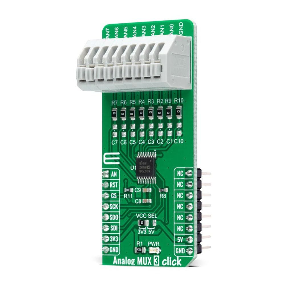
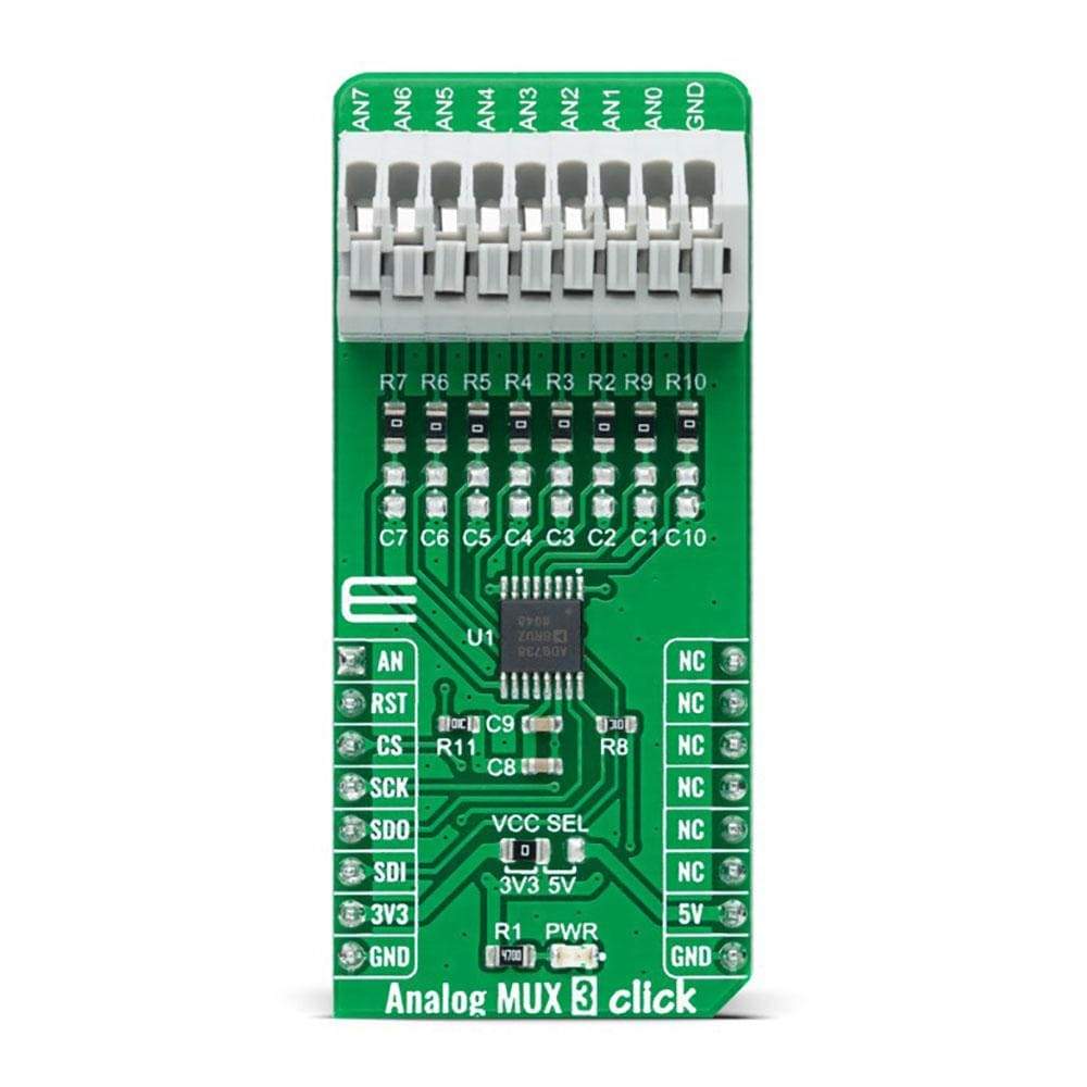
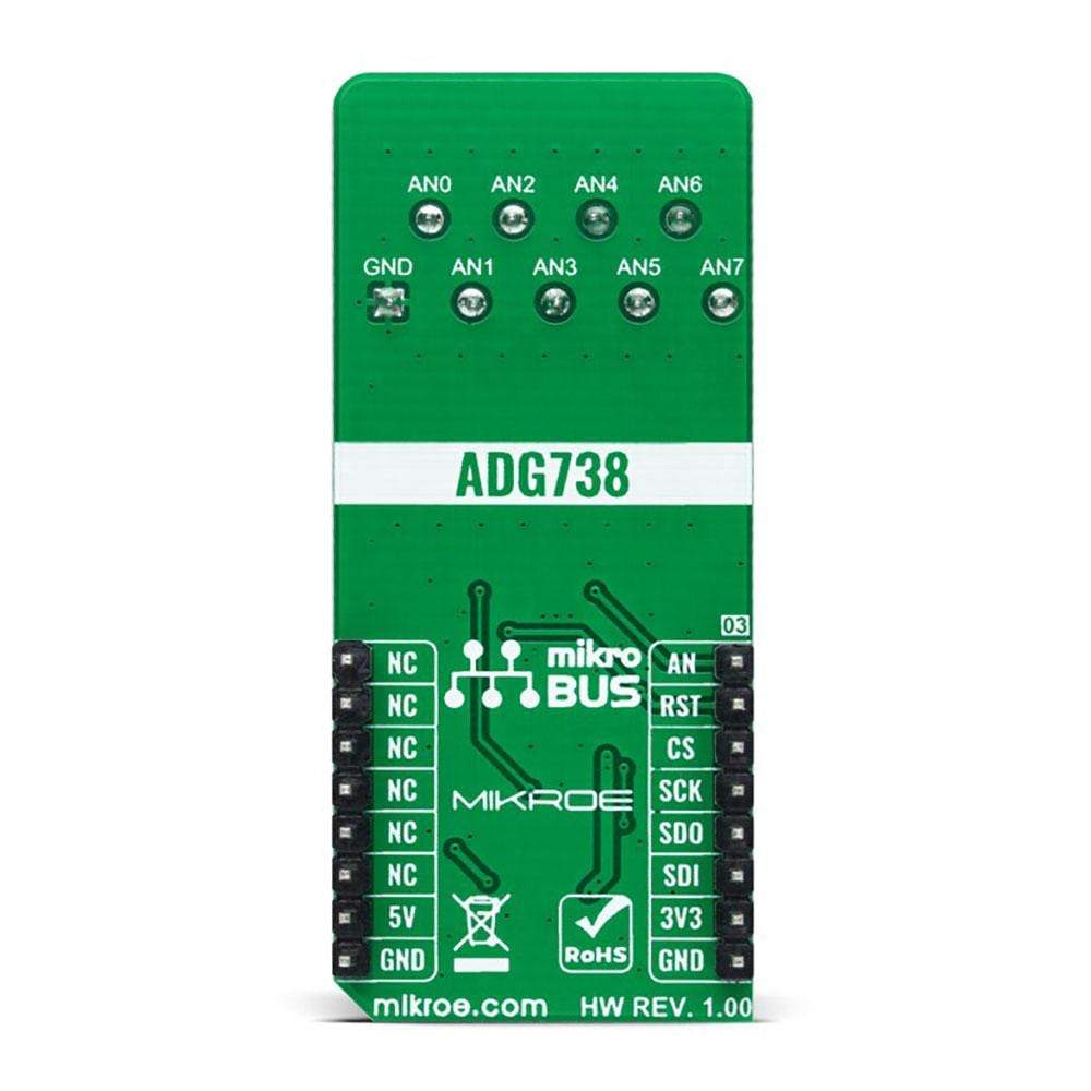
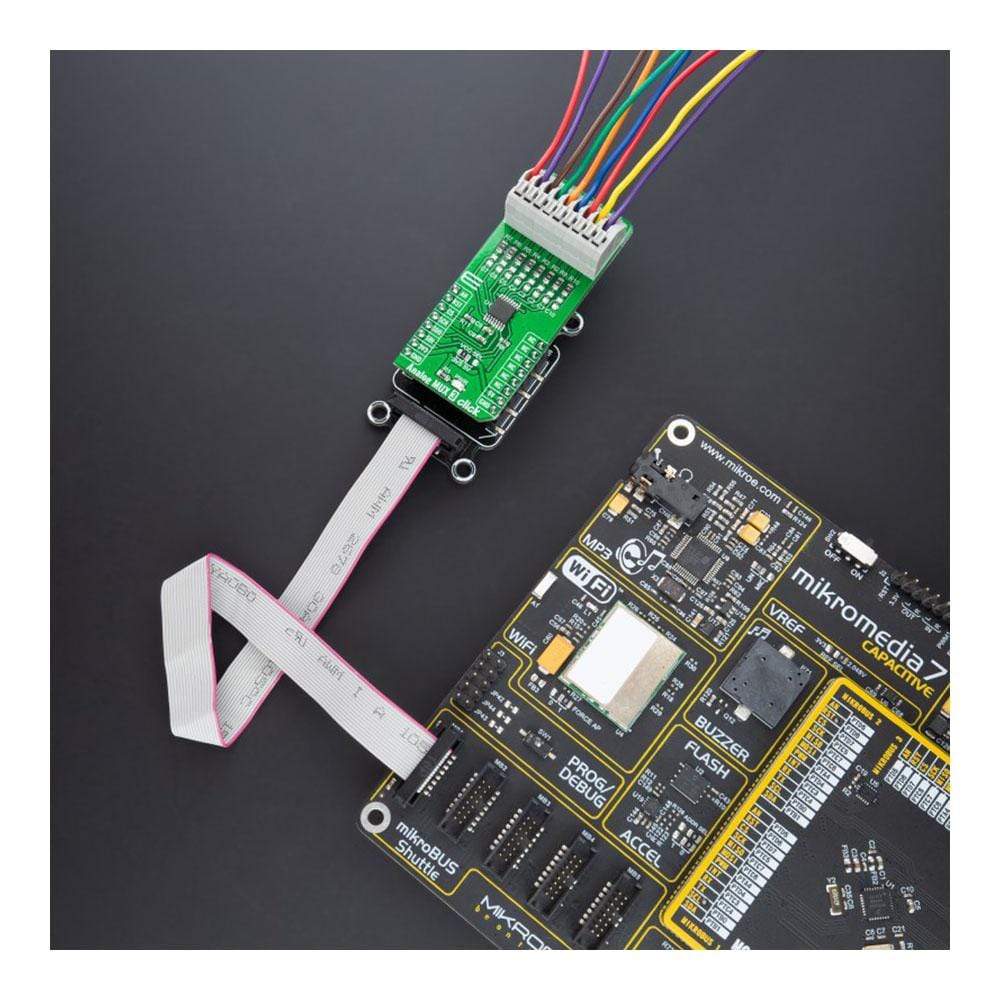
The Analog MUX 3 Click Board™ is a compact add-on board that switches one of the eight inputs to one output. This board features the ADG738, a CMOS analogue matrix switch with a serially-controlled SPI interface from Analog Devices. In an active state, the ADG738 conducts equally well in both directions, making it suitable for multiplexing and demultiplexing applications. It can also be configured as a type of switch array where any, all, or none of eight switches may be closed at any time. All channels exhibit ‘break-before-make switching action, preventing momentary shorting when switching channels. This Click Board™ is suitable for a wide range of applications, from industrial and instrumentation to medical, consumer, communications, and automotive systems.
The Analog MUX 3 Click is supported by a mikroSDK compliant library, which includes functions that simplify software development. This Click Board™ comes as a fully tested product, ready to be used on a system equipped with the mikroBUS™ socket.
Downloads
Der Analog MUX 3 Click Board™ ist eine kompakte Zusatzplatine, die einen der acht Eingänge auf einen Ausgang umschaltet. Diese Platine verfügt über den ADG738, einen CMOS-Analogmatrixschalter mit einer seriell gesteuerten SPI-Schnittstelle von Analog Devices. Im aktiven Zustand leitet der ADG738 in beide Richtungen gleich gut und ist daher für Multiplexing- und Demultiplexing-Anwendungen geeignet. Er kann auch als eine Art Schalterarray konfiguriert werden, bei dem jeder, alle oder keiner der acht Schalter jederzeit geschlossen sein kann. Alle Kanäle weisen eine „Break-Before-Make“-Schaltfunktion auf, die kurzzeitige Kurzschlüsse beim Umschalten der Kanäle verhindert. Dieses Click Board™ ist für eine Vielzahl von Anwendungen geeignet, von Industrie und Instrumentierung bis hin zu medizinischen, Verbraucher-, Kommunikations- und Automobilsystemen.
Der Analog MUX 3 Click wird durch eine mikroSDK-kompatible Bibliothek unterstützt, die Funktionen enthält, die die Softwareentwicklung vereinfachen. Dieses Click Board™ wird als vollständig getestetes Produkt geliefert und ist bereit für den Einsatz auf einem System, das mit der mikroBUS™-Buchse ausgestattet ist.
| General Information | |
|---|---|
Part Number (SKU) |
MIKROE-4580
|
Manufacturer |
|
| Physical and Mechanical | |
Weight |
0.023 kg
|
| Other | |
EAN |
8606027382260
|
Frequently Asked Questions
Have a Question?
Be the first to ask a question about this.