


Mikroelektronika d.o.o.
DTMF-Decoder-Click-Platine
DTMF-Decoder-Click-Platine
SKU: MIKROE-4579
Verfügbarkeit für Abholungen konnte nicht geladen werden
Overview
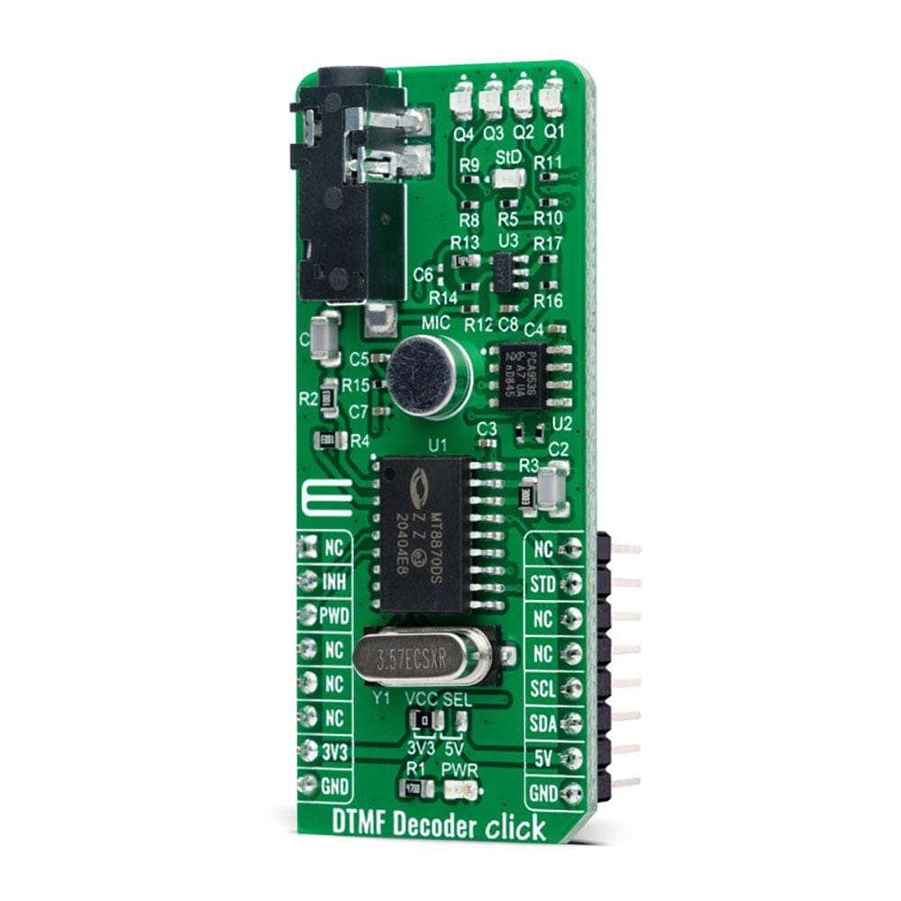
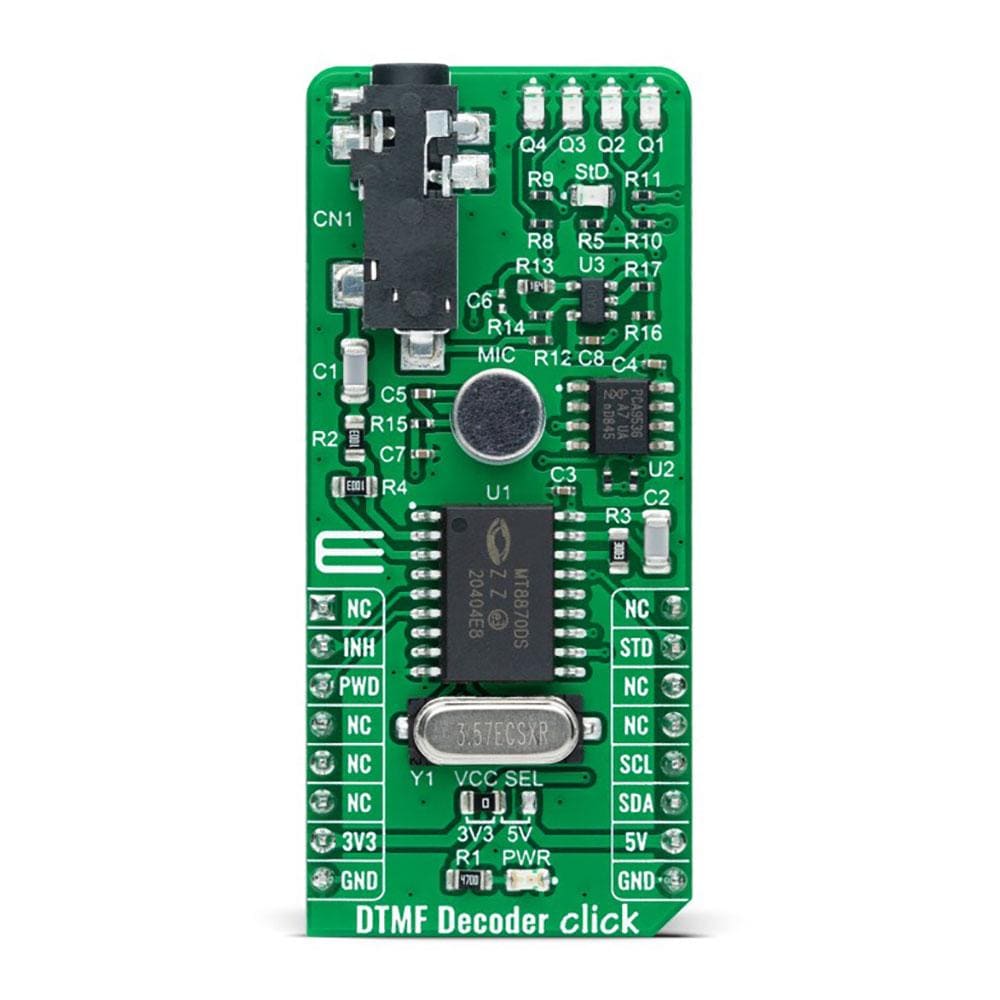
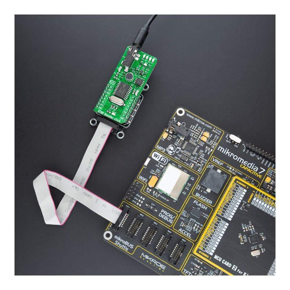
The DTMF Decoder Click Board™ is a compact add-on board that contains an integrated DTMF receiver with enhanced sensitivity. This board features the MT8870D, a complete DTMF receiver integrating the band-split filter and digital decoder functions from Microchip Technology. It offers low power consumption and high performance and uses digital counting techniques to detect and decode all 16 DTMF tone-pairs into a 4-bit code. Whenever a valid tone is detected, it outputs the associated value in binary on four LEDs, with an additional indicator that strobes after each new tone. This Click Board™ is suitable for paging systems, remote control, electronic communications circuits, and various other applications.
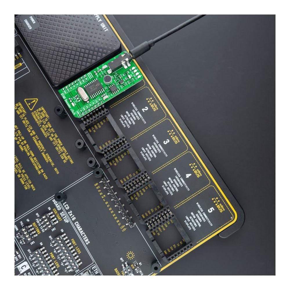
The DTMF Decoder Click Board™ is supported by a mikroSDK compliant library, which includes functions that simplify software development. This Click Board™ comes as a fully tested product, ready to be used on a system equipped with the mikroBUS™ socket.
Downloads
Der DTMF-Decoder Click Board™ ist eine kompakte Zusatzplatine, die einen integrierten DTMF-Empfänger mit erhöhter Empfindlichkeit enthält. Diese Platine verfügt über den MT8870D, einen vollständigen DTMF-Empfänger, der die Bandsplit-Filter- und Digital-Decoder-Funktionen von Microchip Technology integriert. Er bietet einen niedrigen Stromverbrauch und eine hohe Leistung und verwendet digitale Zähltechniken, um alle 16 DTMF-Tonpaare zu erkennen und in einen 4-Bit-Code zu dekodieren. Immer wenn ein gültiger Ton erkannt wird, gibt er den zugehörigen Wert binär auf vier LEDs aus, mit einer zusätzlichen Anzeige, die nach jedem neuen Ton blinkt. Dieses Click Board™ ist für Paging-Systeme, Fernsteuerung, elektronische Kommunikationsschaltungen und verschiedene andere Anwendungen geeignet.
Das DTMF-Decoder Click Board™ wird von einer mikroSDK-kompatiblen Bibliothek unterstützt, die Funktionen enthält, die die Softwareentwicklung vereinfachen. Dieses Click Board™ wird als vollständig getestetes Produkt geliefert und ist bereit für den Einsatz auf einem System, das mit der mikroBUS™-Buchse ausgestattet ist.
| General Information | |
|---|---|
Part Number (SKU) |
MIKROE-4579
|
Manufacturer |
|
| Physical and Mechanical | |
Weight |
0.021 kg
|
| Other | |
EAN |
8606027382291
|
Frequently Asked Questions
Have a Question?
Be the first to ask a question about this.